Installation
Diagram
A
N
L
IS |
| C |
| 1 | |
B |
| |
| 1 | |
| 2 | 3 |
|
| |
| 1 2 3 4 5 6 7 8 |
|
| CnL1 |
|
P
O
ISS
N
CnP3
1
2
3
4
5
6
7
8
CnP1
6
5
4
3
2
1
SCHEDA DI POTENZA
e
CONTROLLO
D
H | F | G 1 |
1/2 | 2 | |
|
| 3 |
CnP2
12
11
10
9
8
7
6
5
4
3
2
1
M
E |
| J |
M | 4 | |
IAQS |
| |
| ML | |
2 | 1 | |
| 2 | |
|
| C |
|
| S |
1
AQS I
1
K
L
RELE'
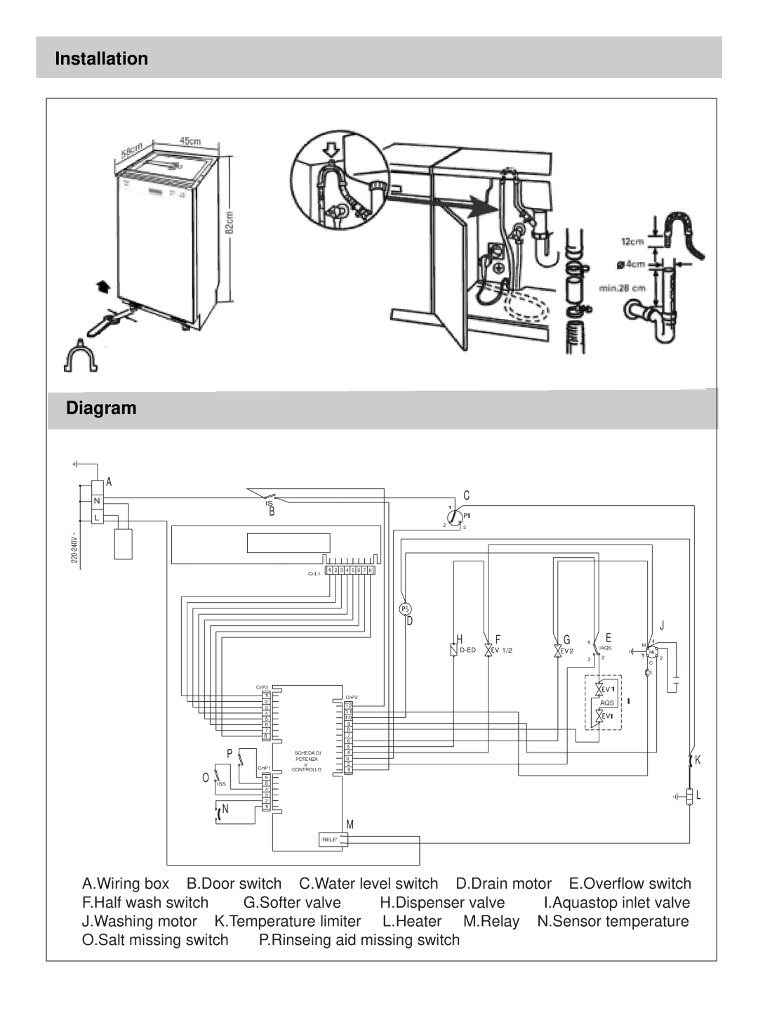
A.Wiring box B.Door switch C.Water level switch | D.Drain motor E.Overflow switch | |||
F.Half wash switch | G.Softer valve | H.Dispenser valve | I.Aquastop inlet valve | |
J.Washing motor K.Temperature limiter | L.Heater | M.Relay | N.Sensor temperature | |
O.Salt missing switch | P.Rinseing aid missing switch |
| ||
