Read owner’s manual. Do not attempt to operate equipment until you have read Owner’s Manual for Safety, Assembly, Operation, Maintenance, Storage Instructions.
TOOLS NEEDED FOR ASSEMBLY
1- Box Cutter or Knife
2 - 9/16 " Wrenches
2 - 1/2" Wrenches
1 - 1" thick x 1' square piece of wood
REMOVE GENERATOR FROM CARTON
•Open carton from top.
•Cut carton along dotted lines.
•Remove all carton inserts.
•Remove generator through opening in carton.
•Using a 9/16 inch socket remove the two shipping blocks from under the generator head. Unscrew the bolts and remove the wood blocks. NOTE: It is very important that these are removed before starting your generator.
IMPORTANT: Before any attempt to start your genera- tor be sure to check engine oil (See Adding Engine Oil paragraph in the Operation section on page 14 of this manual.)
INSTALLATION OF BATTERY
Recommended Battery for Electric Start: 12V - 45 A H. or 210 CCA (Cold Cranking Amps)
Purchase battery and battery hardware separately, not included with unit.
•Place battery in rack with terminals facing towards generator head.
•Place battery bracket (A) over battery as shown (opposite battery terminals).
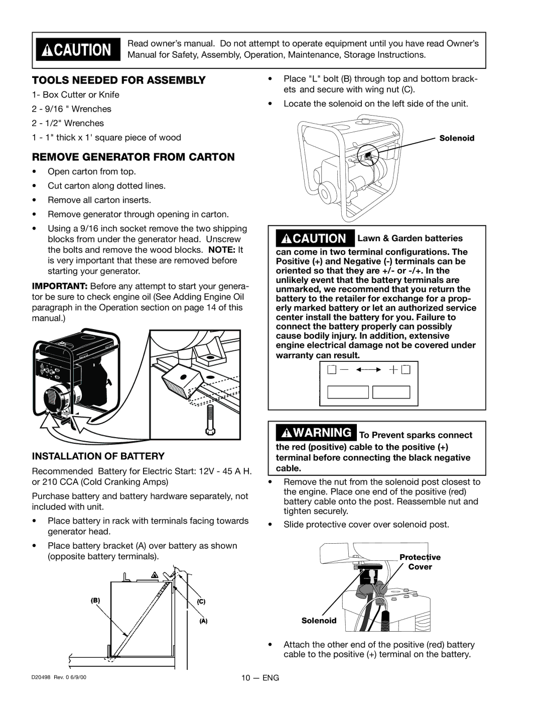
•Place "L" bolt (B) through top and bottom brack- ets and secure with wing nut (C).
•Locate the solenoid on the left side of the unit.
 Solenoid
![]() Lawn & Garden batteries
Lawn & Garden batteries
can come in two terminal configurations. The Positive (+) and Negative
![]() To Prevent sparks connect the red (positive) cable to the positive (+) terminal before connecting the black negative cable.
To Prevent sparks connect the red (positive) cable to the positive (+) terminal before connecting the black negative cable.
•Remove the nut from the solenoid post closest to the engine. Place one end of the positive (red) battery cable onto the post. Reassemble nut and tighten securely.
•Slide protective cover over solenoid post.
Protective
Cover
Solenoid
•Attach the other end of the positive (red) battery cable to the positive (+) terminal on the battery.
D20498 Rev. 0 6/9/00 | 10 — ENG |