2433 specifications
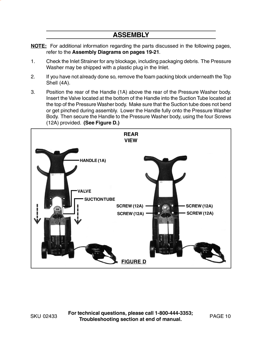
Harbor Freight Tools is widely recognized for providing high-quality, budget-friendly tools for both casual users and professional tradespeople. One notable product in their extensive inventory is the Harbor Freight Tools 2433, a versatile and efficient tool that stands out for its reliability and features.The Harbor Freight Tools 2433 is primarily known as a compact and powerful tool that caters to a range of tasks from woodworking to automotive repairs. One of its main characteristics is its lightweight design, which allows for easy handling and maneuverability, making it an ideal choice for both small and large projects. Weighing in under 5 pounds, it minimizes user fatigue, promoting extended periods of use without discomfort.
A significant feature of the Harbor Freight Tools 2433 is its motor, which delivers impressive torque and speed, ensuring efficient performance. The tool operates at varying RPMs, allowing users to adjust speed according to the specific task at hand, whether it’s drilling, screwing, or cutting. This flexibility makes it an essential tool in any workshop or home garage.
Another noteworthy aspect of this tool is its ergonomic design. The handle is crafted with comfort in mind, providing a secure grip that enhances control during operation. This focus on user experience is complemented by a safety switch that prevents accidental activation, adding an extra layer of protection during use.
Furthermore, the Harbor Freight Tools 2433 is compatible with a wide range of attachments, quickly transforming into a multi-use tool that serves various functions. Whether you need to switch between drill bits or saw blades, the tool's easy-change mechanism simplifies this process, allowing for quick transitions.
The build quality of the Harbor Freight Tools 2433 is also impressive, using durable materials that withstand the rigors of regular use. Users can expect longevity from this tool, making it a worthwhile investment over time.
In summary, the Harbor Freight Tools 2433 embodies versatility, ease of use, and durability. With its powerful motor, ergonomic design, and adaptability through various attachments, it provides an excellent solution for DIY enthusiasts and professionals alike. Whether you’re tackling small home improvement projects or larger construction tasks, this tool stands ready to assist, highlighting Harbor Freight's commitment to quality and affordability in the tool industry.

