1.The air hose must be long enough to reach the work area with enough extra length to allow free movement while working.
2.Turn the tool’s On/Off switch to the “OFF” position; refer to Operation section for description of controls.
3.Inspect the air connections for leaks. Repair any leaks found.
Operating Instructions
Read the entire Important Safety Information section at the beginning of this manual including all text under subheadings therein before set up or use of this product.
Inspect tool before use, looking for damaged, loose, and missing parts. If any problems are found, do not use tool until repaired.
Tool Set Up
To prevent serious injury:
Do not adjust or tamper with any control or component in a way not specifically explained within this manual. Improper adjustment can result in tool failure or other serious hazards.
Work Piece and Work Area Set Up
1.Designate a work area that is clean and
2.Route the air hose along a safe route to reach the work area without creat- ing a tripping hazard or exposing the air hose to possible damage. The air hose must be long enough to reach the work area with enough extra length to allow free movement while working.
General Assembly and Operating
Instructions
1.Set tool on a dry, flat, level surface.
2.To prevent accidents, turn the On/Off Switch (25) to the “OFF” position.
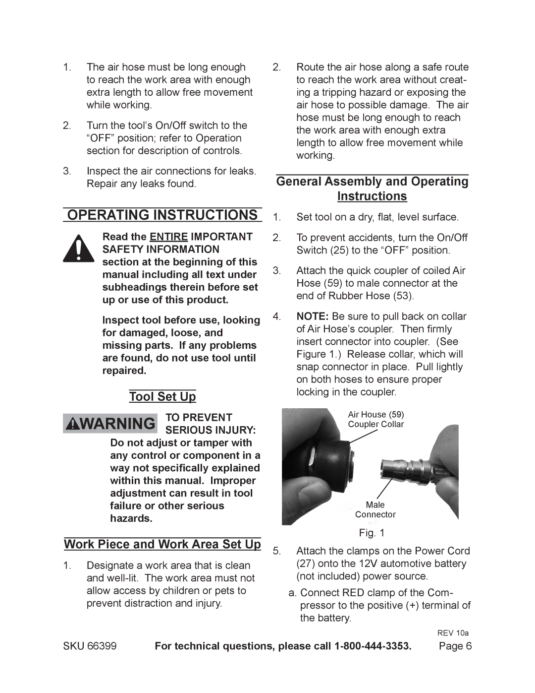
3.Attach the quick coupler of coiled Air Hose (59) to male connector at the end of Rubber Hose (53).
4.NOTE: Be sure to pull back on collar of Air Hose’s coupler. Then firmly insert connector into coupler. (See Figure 1.) Release collar, which will snap connector in place. Pull lightly on both hoses to ensure proper locking in the coupler.
Air House (59)
Coupler Collar
Male
Connector
Fig. 1
5.Attach the clamps on the Power Cord (27) onto the 12V automotive battery (not included) power source.
a.Connect RED clamp of the Com- pressor to the positive (+) terminal of the battery.
REV 10a
SKU 66399 | For technical questions, please call | Page 6 |
