Specifications
y fet Sa
Electrical Rating | 120V~ / 60Hz / 10A |
|
|
Motor No Load Speed | |
|
|
Max. Accessory Diameter | 7″ (178 mm) |
Spindle Thread | 5/8″ x 11 TPI |
| Backing Pad |
Accessories | Foam Pad |
(sold separately) | Polishing Bonnet |
| Sanding Discs |
Setup
no rati Ope
ec
Maintenan
Setup - Before Use:
Read the entire Important Safety Information section at the beginning of this manual including all text under subheadings therein before set up or use of this product.
To prevent serious injury from accidental operation: Release the Trigger and unplug the tool from its electrical outlet before assembling or making any adjustments to the tool.
Note: For additional information regarding the parts listed in the following pages, refer to the Assembly Diagram near the end of this manual.
Assembly
Installing the Auxiliary Handles
TO PREVENT SERIOUS INJURY:
Do not operate this tool with one hand only or without the Auxiliary Handle(s) properly installed.
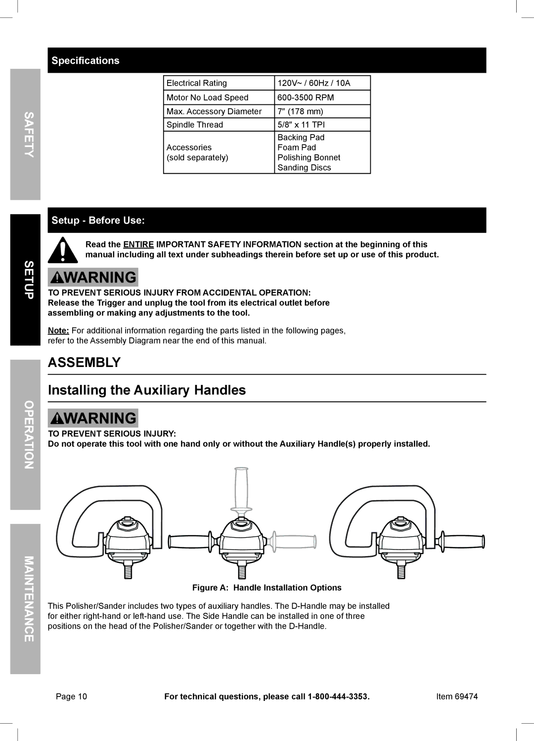
Figure A: Handle Installation Options
This Polisher/Sander includes two types of auxiliary handles. The
Page 10 | For technical questions, please call | Item 69474 |