
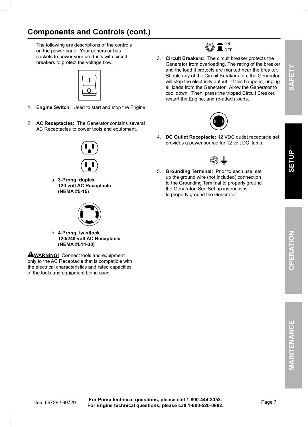
69728 specifications
Harbor Freight Tools 69728 is a versatile and reliable tool that has garnered attention for its efficiency and user-friendly design. This tool is particularly favored by both professionals and DIY enthusiasts for its performance and affordability.One of the standout features of the 69728 is its robust construction. Built with high-quality materials, it ensures longevity and durability, even under heavy usage conditions. This makes it ideal for various tasks, from simple household repairs to more intensive projects. Its design incorporates a rubberized grip, providing maximum comfort while reducing fatigue during extended use.
The Harbor Freight 69728 comes equipped with a powerful motor that enhances its overall performance. This motor operates smoothly, facilitating various applications without compromising speed or effectiveness. Additionally, the tool is designed to offer variable speed settings, allowing users to adjust the speed according to the requirements of their specific task. This feature adds versatility, making it suitable for intricate jobs that demand precision as well as more extensive applications that require power.
Another significant characteristic of the 69728 is its lightweight design. Weighing significantly less than comparable tools on the market, it offers ease of handling and portability. This makes it an excellent choice for those who frequently move between jobs or require a tool that can easily be transported.
Safety is a priority with the Harbor Freight 69728, and it includes several safety features that provide peace of mind during operation. The built-in safety trigger prevents accidental starts, ensuring the tool is only activated when the user intends to use it.
In terms of technological advancements, the 69728 integrates modern engineering with a focus on user efficiency. It features easy-to-use controls that are intuitive, minimizing the learning curve for beginners while still providing seasoned users with reliable functionality.
Overall, the Harbor Freight Tools 69728 stands out as a formidable option for anyone seeking a dependable and high-quality tool. Its combination of power, durability, user comfort, and safety features positions it as a valuable addition to any toolkit. Whether you are a professional contractor or a weekend hobbyist, the 69728 is engineered to meet your needs and exceed your expectations.