PARTS LIST
Part # | Description | Part # | Description | Par | Description |
|
|
|
| t # |
|
1 | Belt Guard Inner | 16 | Air Tube | 31 | Air Tank |
2 | Screw | 17 | Bolt | 32 | Nut |
3 | Washer | 18 | Flat Washer | 33 | Bolt |
4 | Belt Guard Outer | 19 | Spring Washer | 34 | Rubber Foot |
5 | Gasoline Engine * | 20 | Nut | 35 | Pneumatic Tire |
6 | Washer | 21 | Control Wire | 36 | Axle |
7 | Nut | 22 | Control Valve Assembly | 37 | Washer |
8 | Belt Pulley (Engine) | 23 | Handle Grip | 38 | Lock Pin |
9 | Belt | 24 | Handle | 39 | Spring Washer |
10 | Bolt | 25 | Air Pressure Regulator | 40 | Flat Washer |
11 | Nut | 26 | Hose Connector (output) | 41 | Bolt |
12 | Support Bar | 27 | Pressure Gauge (output) | 42 | Safety Valve |
13 | Nut | 28 | Water Drainer | 43 | |
14 | Washer | 29 | Washer | 44 | Pressure Gauge (Tank) |
15 | Compressor Pump | 30 | Screw | 45 | Handle Bracket |
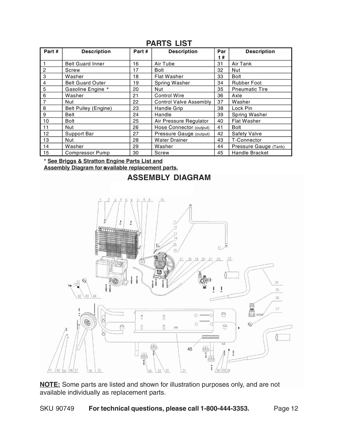
*See Briggs & Stratton Engine Parts List and Assembly Diagram for ®available replacement parts.
ASSEMBLY DIAGRAM
45
NOTE: Some parts are listed and shown for illustration purposes only, and are not available individually as replacement parts.
SKU 90749 | For technical questions, please call | Page 12 |