7.Connect the air hose (not provided) to the previously installed 3/8” NPT Quick Coupler on the Air Outlet Line. Then, connect the other end of the air hose to the pneumatic tool or equipment (not provided) that is to be used.
8.Start the Gasoline Engine (5). Refer to the Gasoline Engine manufacturer’s instruction manual for further information.
9.Allow sufficient time for the Air Tanks’ Pressure Gauge (27) to indicate at least 80 PSI before using the Air Compressor. (See Figure I.)
AIR FILTER (B4) SAFETY COVER (31)
CONTROL VALVE ASSEMBLY
(22)
PRESSURE GAUGE
(44)
AIR OUTLET LINE
GASOLINE ENGINE (5)
PRESSURE GAUGE (27) SAFETY VALVE (42)
TIRE (35)
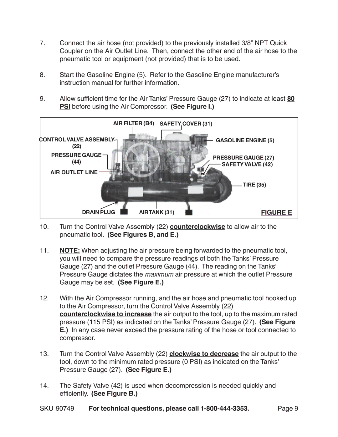
DRAIN PLUG | AIRTANK (31) | FIGURE E |
10.Turn the Control Valve Assembly (22) counterclockwise to allow air to the pneumatic tool. (See Figures B, and E.)
11.NOTE: When adjusting the air pressure being forwarded to the pneumatic tool, you will need to compare the pressure readings of both the Tanks’ Pressure Gauge (27) and the outlet Pressure Gauge (44). The reading on the Tanks’ Pressure Gauge dictates the maximum air pressure at which the outlet Pressure Gauge may be set. (See Figure E.)
12.With the Air Compressor running, and the air hose and pneumatic tool hooked up to the Air Compressor, turn the Control Valve Assembly (22) counterclockwise to increase the air output to the tool, up to the maximum rated pressure (115 PSI) as indicated on the Tanks’ Pressure Gauge (27). (See Figure E.) In any case never exceed the pressure rating of the hose or tool connected to compressor.
13.Turn the Control Valve Assembly (22) clockwise to decrease the air output to the tool, down to the minimum rated pressure (0 PSI) as indicated on the Tanks’ Pressure Gauge (27). (See Figure E.)
14.The Safety Valve (42) is used when decompression is needed quickly and efficiently. (See Figure B.)
SKU 90749 | For technical questions, please call | Page 9 |
