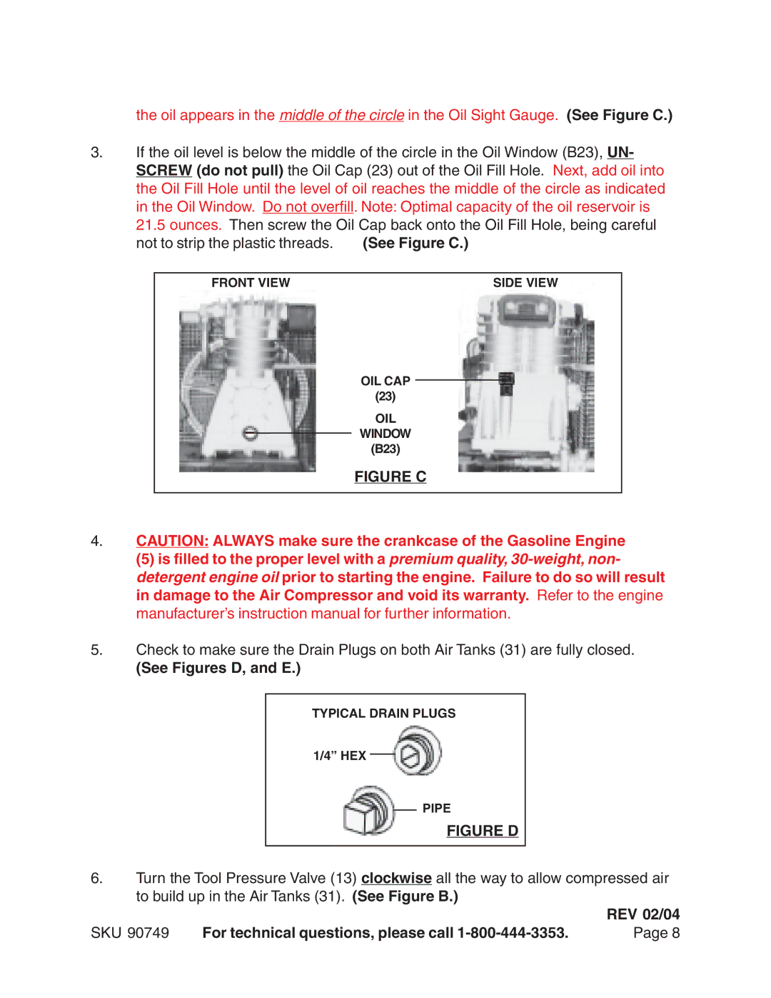
the oil appears in the middle of the circle in the Oil Sight Gauge. (See Figure C.)
3.If the oil level is below the middle of the circle in the Oil Window (B23), UN- SCREW (do not pull) the Oil Cap (23) out of the Oil Fill Hole. Next, add oil into the Oil Fill Hole until the level of oil reaches the middle of the circle as indicated in the Oil Window. Do not overfill. Note: Optimal capacity of the oil reservoir is
21.5 ounces. Then screw the Oil Cap back onto the Oil Fill Hole, being careful
not to strip the plastic threads. | (See Figure C.) | |
|
|
|
| FRONT VIEW | SIDE VIEW |
OIL CAP
(23)
OIL
WINDOW
(B23)
FIGURE C
4.CAUTION: ALWAYS make sure the crankcase of the Gasoline Engine
(5) is filled to the proper level with a premium quality,
5.Check to make sure the Drain Plugs on both Air Tanks (31) are fully closed.
(See Figures D, and E.)
TYPICAL DRAIN PLUGS
1/4” HEX
PIPE
FIGURE D
6.Turn the Tool Pressure Valve (13) clockwise all the way to allow compressed air to build up in the Air Tanks (31). (See Figure B.)
|
| REV 02/04 |
SKU 90749 | For technical questions, please call | Page 8 |