ASSEMBLY INSTRUCTIONS
NOTE: For additional references to the parts listed in the following pages, refer to the
Assembly Diagram on page 12 and 13.
Note: The only assembly required is as follows.
A.Put on front Tire (35): An Washer (37) goes on each side of Tire and Axle (36) fits through hub of wheel. Insert Pin Lock (38) to keep wheel in place. Front Axle fits into Wheel Brackets (50) and is secured in place by two Bolts (part #41) with Washer (40), which are threaded into the hole in each Wheel Bracket.
B.Each Handle (24) fits into the Handle Bracket (45) on the side of the Air Tank (31). Secure each Handle in place with 2 Washer/Screw combinations (29 and 30). After assembly is complete test the
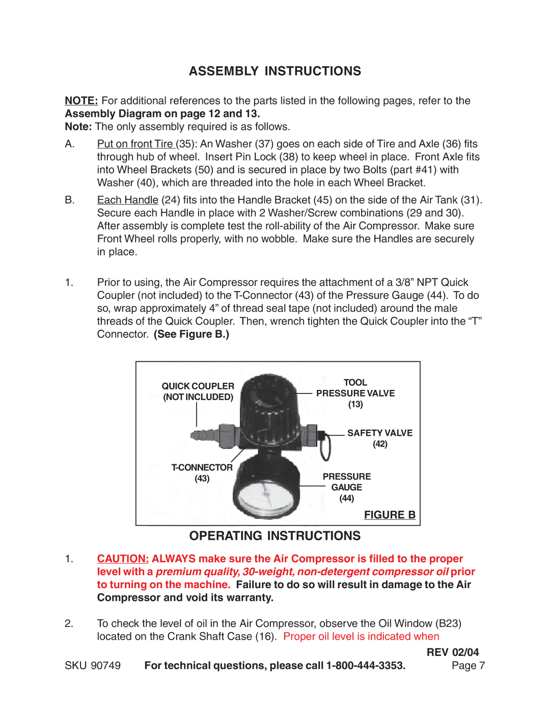
1.Prior to using, the Air Compressor requires the attachment of a 3/8” NPT Quick Coupler (not included) to the
QUICK COUPLER |
|
| TOOL | |||
| PRESSURE VALVE | |||||
(NOT INCLUDED) |
| |||||
| ||||||
(13) | ||||||
|
| |||||
|
|
|
|
| SAFETY VALVE | |
|
|
|
|
| ||
|
|
|
|
| ||
|
| (42) | ||||
|
| PRESSURE | ||||
(43) |
|
| ||||
|
|
|
| GAUGE | ||
|
| (44) | ||||
|
|
|
|
| FIGURE B | |
OPERATING INSTRUCTIONS
1.CAUTION: ALWAYS make sure the Air Compressor is filled to the proper level with a premium quality,
2.To check the level of oil in the Air Compressor, observe the Oil Window (B23) located on the Crank Shaft Case (16). Proper oil level is indicated when
|
| REV 02/04 |
SKU 90749 | For technical questions, please call | Page 7 |
