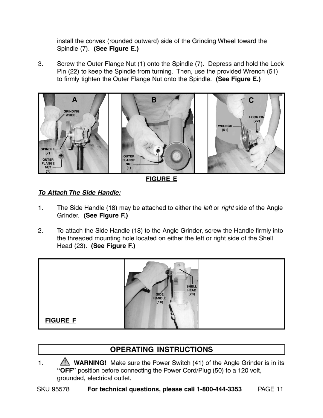
install the convex (rounded outward) side of the Grinding Wheel toward the Spindle (7). (See Figure E.)
3.Screw the Outer Flange Nut (1) onto the Spindle (7). Depress and hold the Lock Pin (22) to keep the Spindle from turning. Then, use the provided Wrench (51) to firmly tighten the Outer Flange Nut onto the Spindle. (See Figure E.)
A
GRINDING
WHEEL
SPINDLE
(7)
OUTER
FLANGE
NUT
(1)
B
OUTER
FLANGE
NUT
(1)
C
LOCK PIN
(22)
WRENCH
(51)
FIGURE E
To Attach The Side Handle:
1.The Side Handle (18) may be attached to either the left or right side of the Angle Grinder. (See Figure F.)
2.To attach the Side Handle (18) to the Angle Grinder, screw the Handle firmly into the threaded mounting hole located on either the left or right side of the Shell Head (23). (See Figure F.)
SHELL
HEAD
SIDE
(23)
FIGURE F
HANDLE
(18)
OPERATING INSTRUCTIONS
1.![]() WARNING! Make sure the Power Switch (41) of the Angle Grinder is in its “OFF” position before connecting the Power Cord/Plug (50) to a 120 volt, grounded, electrical outlet.
WARNING! Make sure the Power Switch (41) of the Angle Grinder is in its “OFF” position before connecting the Power Cord/Plug (50) to a 120 volt, grounded, electrical outlet.
SKU 95578 For technical questions, please call