R-410A specifications
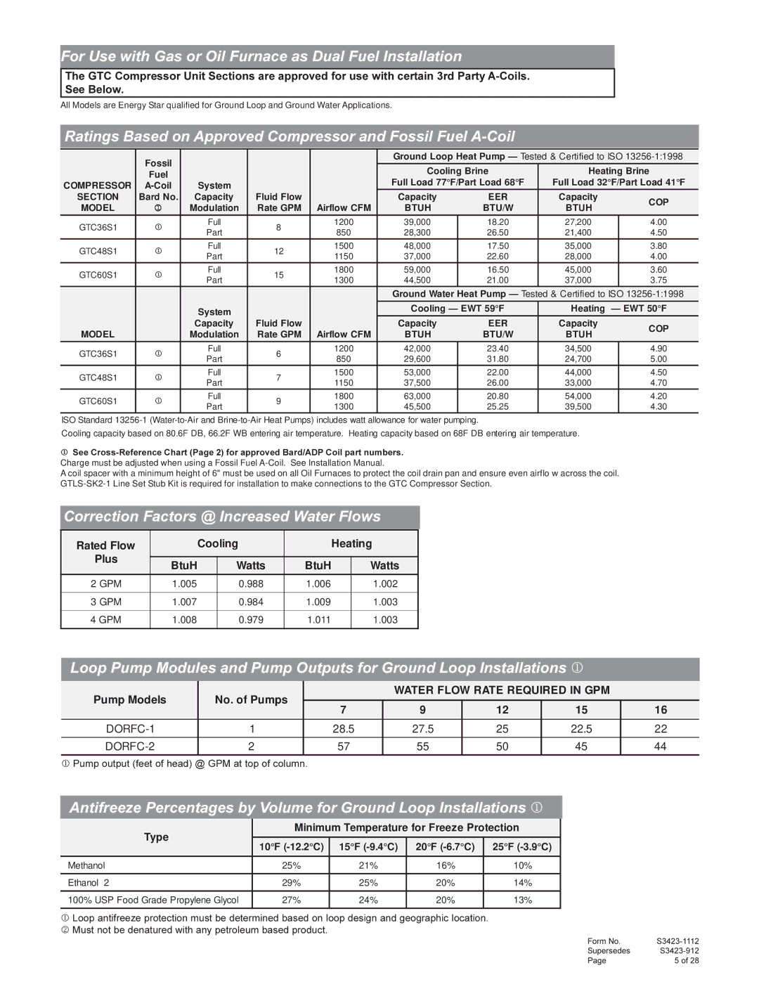
Harbor Freight Tools R-410A is a high-quality refrigerant that has become essential for modern air conditioning systems. Designed specifically for use in HVAC applications, R-410A is a hydrofluorocarbon (HFC) refrigerant that plays a crucial role in energy efficiency and improved environmental performance. One of its standout characteristics is its ability to operate at a higher pressure than older refrigerants like R-22, making it an ideal choice for new systems and retrofits.One of the main features of Harbor Freight Tools R-410A is its excellent thermodynamic properties, which contribute to improved cooling efficiency. The refrigerant boasts a high latent heat of vaporization, allowing it to absorb and release significant amounts of heat during the compression and evaporation processes. This efficiency translates to lower operational costs and reduced energy consumption, making it a popular choice for environmentally conscious consumers and businesses alike.
In terms of safety, R-410A is non-toxic and non-flammable, addressing concerns associated with certain older refrigerants. This aspect is particularly important in residential and commercial settings, where the safety of occupants is paramount. Furthermore, R-410A has a zero ozone depletion potential (ODP), aligning with global initiatives to phase out substances that are harmful to the atmosphere.
Harbor Freight Tools R-410A is also compatible with various lubricants and doesn't require the use of mineral oil, which is essential when retrofitting older systems. The refrigerant’s unique blend allows for seamless operation in systems designed to operate at high efficiency.
With a boiling point of approximately -51 degrees Celsius, R-410A works effectively in a wide temperature range, making it suitable for various cooling and heating applications. This versatility ensures that users can rely on this refrigerant for both residential air conditioning units and commercial systems alike.
Overall, Harbor Freight Tools R-410A stands out as a modern solution for HVAC needs, combining efficiency, safety, and environmental responsibility. Its innovative characteristics and features make it a go-to choice for both contractors and DIY enthusiasts looking to optimize their air conditioning systems while adhering to current environmental standards. The continued adoption of R-410A underscores the ongoing evolution of the HVAC industry, catering to the needs of a more eco-conscious market.

