dbx 160A COMPRESSOR / LIMITER
CONNECTING THE 160A TO YOUR SYSTEM
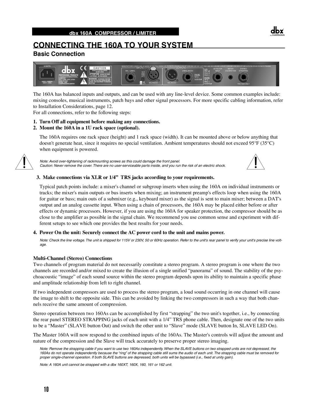
Basic Connection
| 15 WATTS |
| ||
|
|
|
| A HARMAN INTERNATIONAL |
|
|
|
| |
|
|
|
| |
|
|
|
| |
|
|
|
| |
|
|
|
| |
|
|
|
| COMPANY |
|
|
|
| SALT LAKE CITY, UTAH |
100V | 50/60Hz | MADE IN USA | ||
120V |
| 60Hz | MODEL 160A | |
|
|
|
| COMPRESSOR/LIMITER |
MANUFACTURED UNDER ONE OR MORE OF THE FOLLOWING U.S. PATENTS 4,234,804 4,316,107 4,329,598 4,331,931 4,377,792 4,403,199 4,409,500 4,425,551 4,434,380 4,454,433 4,471,324 4,473,793 OTHER PATENTS PENDING | |||||||
| INPUTS |
| OUTPUTS | XLR: | DETECTOR | METER | STEREO |
|
|
|
| ||||
BAL / UNBAL | XLR |
| UNBALANCED | PIN 1 | INPUT | CALIBRATION | STRAPPING |
|
|
| PIN 2 |
|
|
| |
| GND |
| PHONE: |
|
|
| |
|
| PIN 3 |
|
|
| ||
| LIFT |
|
|
|
| ||
|
| TIP | PHONE: |
|
|
| |
|
|
|
|
|
| ||
|
|
| SLEEVE |
|
|
| |
|
|
| TIP |
|
|
| |
|
| BALANCED | BALANCED | RING |
|
|
|
| LIFT | SLEEVE |
|
| TRS 160A ONLY | ||
|
|
|
|
| |||
The 160A has balanced inputs and outputs, and can be used with any
For all connections, refer to the following steps:
1.Turn Off all equipment before making any connections.
2.Mount the 160A in a 1U rack space (optional).
The 160A requires one rack space (height) and 1 rack space (width). It can be mounted above or below anything that doesn't generate heat, since it requires no special ventilation. Ambient temperatures should not exceed 95°F (35°C) when equipment is powered..
Note: Avoid
Caution: Never remove the cover. There are no
3. Make connections via XLR or 1/4” TRS jacks according to your requirements.
Typical patch points include: a mixer's channel or subgroup inserts when using the 160A on individual instruments or tracks; the mixer's main outputs or bus inserts when mixing; an instrument preamp's effects loop when using the 160A for guitar or bass; main outs of a submixer (e.g., keyboard mixer) as the signal is sent to main mixer; between a DAT's output and an analog cassette input. When using a chain of processors, the 160A may be placed either before or after effects or dynamic processors. However, if you are using the 160A for speaker protection, the compressor should be as close to the amplifier as possible in the signal chain. We recommend you use common sense and experiment with dif- ferent setups to see which one provides the best results for your needs.
4. Power On the unit: Securely connect the AC power cord to the unit and mains power.
Note: Check the line voltage. The unit is shipped for 115V or 230V, 50 or 60Hz operation. Refer to the unit's rear panel to verify your unit's precise line volt- age.
Two channels of program material do not necessarily constitute a stereo program. A stereo program is one where the two channels are recorded and/or mixed to create the illusion of a single unified “panorama” of sound. The stability of the psy- choacoustic “image” of each sound source within the stereo program depends upon its ability to maintain a specific phase and amplitude relationship from left to right channel..
If two independent compressors are used to process the stereo program, a loud sound occurring in one channel will cause the image to shift to the opposite side. This can be avoided by linking the two compressors in such a way that both chan- nels receive the same amount of compression.
Stereo operation between two 160As can be accomplished by first “strapping” the two unit's together, i.e., by connecting the rear panel STEREO STRAPPING jacks of each unit with a 1/4” TRS phone cable. Then, designate one of the two units to be a “Master” (SLAVE button Out) and switch the other unit to “Slave” mode (SLAVE button In, SLAVE LED On).
The Master 160A will now respond to the combined inputs of the 160As. The Master's controls will adjust the amount and nature of the compression and the Slave will track accurately to preserve proper stereo imaging.
Note: Remove the strapping cable if you want to use two 160As independently. When the SLAVE buttons on two strapped units are not depressed, the 160As do not operate independently because the “ring” of the strapping cable still sums the audio of each unit. The strapping cable must be removed for proper
Note: A 160A unit cannot be strapped with a dbx 160XT, 160X, 160, 161 or 162 unit.
10