3.Carefully remove the protective plastic film from the front-panel lens. If left in place, the film will prevent proper operation of the remote control.
4.Install the four supplied AAA batteries in the remote as shown. Be certain to follow the (+) and (–) polarity indicators that are in the battery compartment.
5. Turn the AVR 430 on either by pressing the Standby/On Switch 1 on the front panel, or via the remote by pressing the Power On Button b, the AVR Selector e∫ or any of the
Input Selectors 3 ç∂ on the remote. The lighting around the Standby/On Switch 1 will turn blue to confirm that the unit is on.
Using the On-Screen Display
When making the following adjustments, you may find it easier to use the AVR 430’s on-screen display sys- tem. These easy-to-read displays give you a clear pic- ture of the current status of the unit and make it easy to see which speaker, delay, input or digital selection you are making.
To view the on-screen menus, make certain you have made a connection from the Video Monitor Out Jack › on the rear panel to the composite or S- Video input of your TV or projector. In order to view the AVR 430’s displays, the correct video source must be selected on the video display. The on-screen menus are not available when a component video display is in use.
IMPORTANT NOTE: When viewing the on-screen menus using a CRT-based projector, plasma display or direct-view CRT monitor or television, it is important that they not be left on for an extended period of time. The constant display of a static image such as these menus may cause the image to be permanently “burned into” the projection tubes, plasma screen or CRT. This type of damage is not covered by the AVR 430 warranty and may not be covered by the projector/TV set’s warranty.
The AVR 430 has two on-screen display modes, “Semi-OSD” and “Full-OSD.” When making configura- tion adjustments, it is recommended that the full-OSD mode be used. This will place an easily viewed list of the available options on the screen.
Making Configuration Adjustments
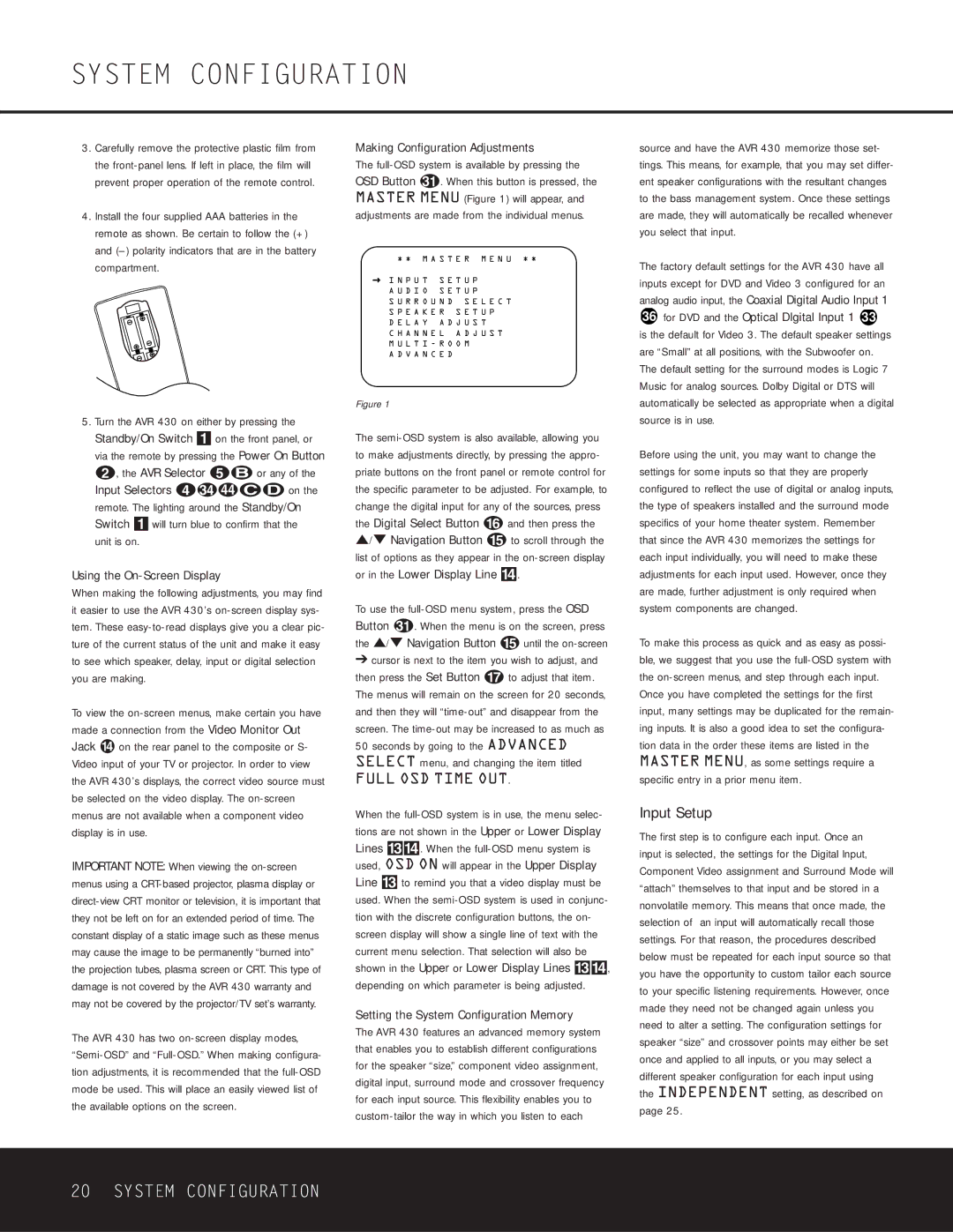
The full-OSD system is available by pressing the
OSD Button . When this button is pressed, the MASTER MENU (Figure 1) will appear, and adjustments are made from the individual menus.
* * M A S T E R M E N U * *
→ I N P U T S E T U P A U D I O S E T U P
S U R R O U N D S E L E C T S P E A K E R S E T U P
D E L A Y A D J U S T
C H A N N E L A D J U S T M U L T I - R O O M
A D V A N C E D
Figure 1
The semi-OSD system is also available, allowing you to make adjustments directly, by pressing the appro- priate buttons on the front panel or remote control for the specific parameter to be adjusted. For example, to change the digital input for any of the sources, press the Digital Select Button p and then press the ⁄/¤ Navigation Button o to scroll through the list of options as they appear in the on-screen display or in the Lower Display Line $.
To use the full-OSD menu system, press the OSD
Button . When the menu is on the screen, press the ⁄/¤ Navigation Button o until the on-screen
➔cursor is next to the item you wish to adjust, and then press the Set Button q to adjust that item. The menus will remain on the screen for 20 seconds, and then they will “time-out” and disappear from the screen. The time-out may be increased to as much as 50 seconds by going to the ADVANCED SELECT menu, and changing the item titled
FULL OSD TIME OUT.
When the full-OSD system is in use, the menu selec- tions are not shown in the Upper or Lower Display Lines #$. When the full-OSD menu system is used, OSD ON will appear in the Upper Display Line # to remind you that a video display must be used. When the semi-OSD system is used in conjunc- tion with the discrete configuration buttons, the on- screen display will show a single line of text with the current menu selection. That selection will also be shown in the Upper or Lower Display Lines #$, depending on which parameter is being adjusted.
Setting the System Configuration Memory
The AVR 430 features an advanced memory system that enables you to establish different configurations for the speaker “size,” component video assignment, digital input, surround mode and crossover frequency for each input source. This flexibility enables you to custom-tailor the way in which you listen to each
source and have the AVR 430 memorize those set- tings. This means, for example, that you may set differ- ent speaker configurations with the resultant changes to the bass management system. Once these settings are made, they will automatically be recalled whenever you select that input.
The factory default settings for the AVR 430 have all inputs except for DVD and Video 3 configured for an analog audio input, the Coaxial Digital Audio Input 1
36for DVD and the Optical DIgital Input 1 33
is the default for Video 3. The default speaker settings are “Small” at all positions, with the Subwoofer on. The default setting for the surround modes is Logic 7 Music for analog sources. Dolby Digital or DTS will automatically be selected as appropriate when a digital source is in use.
Before using the unit, you may want to change the settings for some inputs so that they are properly configured to reflect the use of digital or analog inputs, the type of speakers installed and the surround mode specifics of your home theater system. Remember that since the AVR 430 memorizes the settings for each input individually, you will need to make these adjustments for each input used. However, once they are made, further adjustment is only required when system components are changed.
To make this process as quick and as easy as possi- ble, we suggest that you use the full-OSD system with the on-screen menus, and step through each input.
Once you have completed the settings for the first input, many settings may be duplicated for the remain- ing inputs. It is also a good idea to set the configura- tion data in the order these items are listed in the MASTER MENU, as some settings require a specific entry in a prior menu item.
Input Setup
The first step is to configure each input. Once an input is selected, the settings for the Digital Input, Component Video assignment and Surround Mode will “attach” themselves to that input and be stored in a nonvolatile memory. This means that once made, the selection of an input will automatically recall those settings. For that reason, the procedures described below must be repeated for each input source so that you have the opportunity to custom tailor each source to your specific listening requirements. However, once made they need not be changed again unless you need to alter a setting. The configuration settings for speaker “size” and crossover points may either be set once and applied to all inputs, or you may select a different speaker configuration for each input using the INDEPENDENT setting, as described on page 25.