Section 5 - Installing the AL400 Fully Powered Lift
•You should have established a mounting position for the lift during the “trial fit” as described in Section #2 of this manual. If not, it is recommended that you go through that procedure.
Note: The Base should be mounted as far to the rear corner of the vehicle as possible in most rear mount applications.
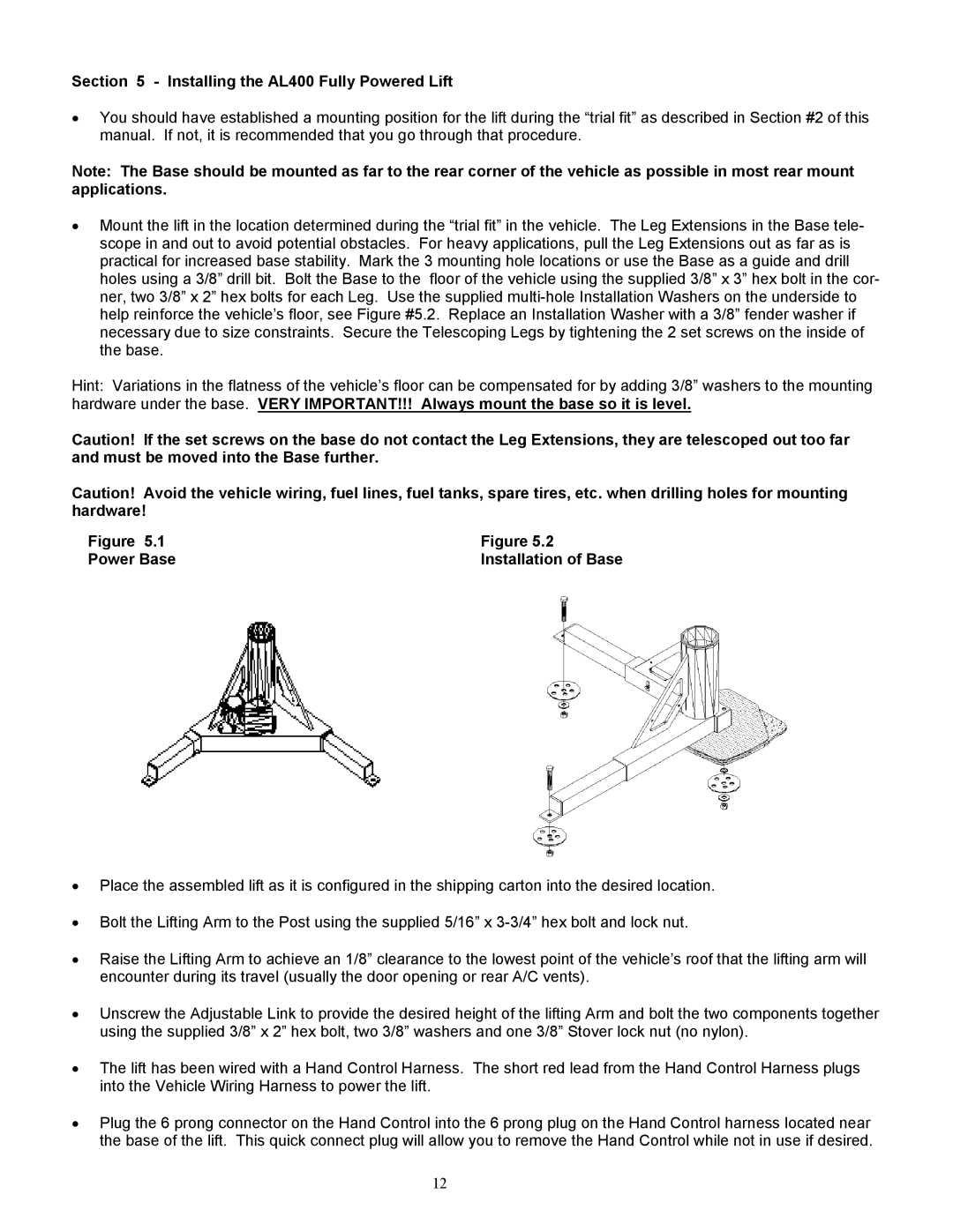
•Mount the lift in the location determined during the “trial fit” in the vehicle. The Leg Extensions in the Base tele- scope in and out to avoid potential obstacles. For heavy applications, pull the Leg Extensions out as far as is practical for increased base stability. Mark the 3 mounting hole locations or use the Base as a guide and drill holes using a 3/8” drill bit. Bolt the Base to the floor of the vehicle using the supplied 3/8” x 3” hex bolt in the cor- ner, two 3/8” x 2” hex bolts for each Leg. Use the supplied
Hint: Variations in the flatness of the vehicle’s floor can be compensated for by adding 3/8” washers to the mounting hardware under the base. VERY IMPORTANT!!! Always mount the base so it is level.
Caution! If the set screws on the base do not contact the Leg Extensions, they are telescoped out too far and must be moved into the Base further.
Caution! Avoid the vehicle wiring, fuel lines, fuel tanks, spare tires, etc. when drilling holes for mounting hardware!
Figure 5.1 | Figure 5.2 |
Power Base | Installation of Base |
•Place the assembled lift as it is configured in the shipping carton into the desired location.
•Bolt the Lifting Arm to the Post using the supplied 5/16” x
•Raise the Lifting Arm to achieve an 1/8” clearance to the lowest point of the vehicle’s roof that the lifting arm will encounter during its travel (usually the door opening or rear A/C vents).
•Unscrew the Adjustable Link to provide the desired height of the lifting Arm and bolt the two components together using the supplied 3/8” x 2” hex bolt, two 3/8” washers and one 3/8” Stover lock nut (no nylon).
•The lift has been wired with a Hand Control Harness. The short red lead from the Hand Control Harness plugs into the Vehicle Wiring Harness to power the lift.
•Plug the 6 prong connector on the Hand Control into the 6 prong plug on the Hand Control harness located near the base of the lift. This quick connect plug will allow you to remove the Hand Control while not in use if desired.
12