FRAME ASSEMBLY
ARM ASSEMBLY
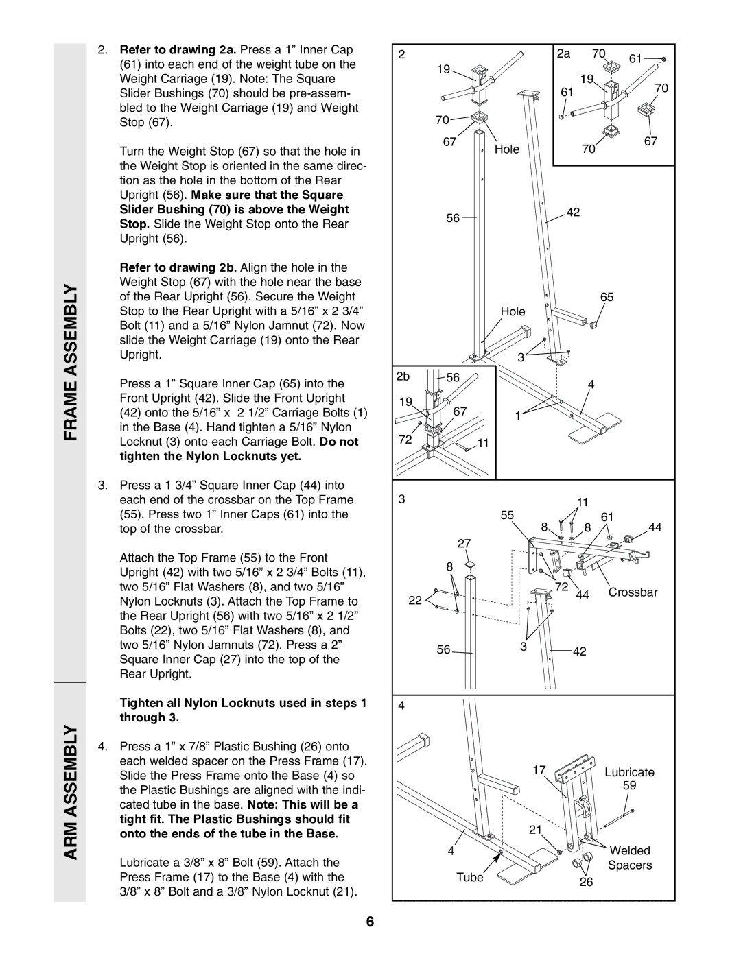
2. Refer to drawing 2a. Press a 1” Inner Cap | 2 |
| 2a | 70 | 61 | |
(61) into each end of the weight tube on the |
| |||||
| 19 |
|
|
| ||
|
|
|
|
| ||
Weight Carriage (19). Note: The Square |
|
| 19 |
|
| |
|
|
|
| 70 | ||
Slider Bushings (70) should be |
|
| 61 |
| ||
|
|
|
| |||
bled to the Weight Carriage (19) and Weight |
| 70 |
|
|
|
|
Stop (67). |
|
|
|
|
| |
Turn the Weight Stop (67) so that the hole in |
| 67 | Hole | 70 |
| 67 |
|
|
|
| |||
the Weight Stop is oriented in the same direc- |
|
|
|
|
|
|
tion as the hole in the bottom of the Rear |
|
|
|
|
|
|
Upright (56). Make sure that the Square |
|
|
|
|
|
|
Slider Bushing (70) is above the Weight |
| 56 | 42 |
|
| |
Stop. Slide the Weight Stop onto the Rear |
|
|
|
|
| |
|
|
|
|
|
| |
Upright (56). |
|
|
|
|
|
|
Refer to drawing 2b. Align the hole in the |
|
|
|
|
|
|
Weight Stop (67) with the hole near the base |
|
|
|
|
|
|
of the Rear Upright (56). Secure the Weight |
|
|
|
| 65 | |
Stop to the Rear Upright with a 5/16” x 2 3/4” |
|
| Hole |
|
|
|
Bolt (11) and a 5/16” Nylon Jamnut (72). Now |
|
|
|
|
|
|
slide the Weight Carriage (19) onto the Rear |
|
|
|
|
|
|
Upright. |
|
| 3 |
|
|
|
Press a 1” Square Inner Cap (65) into the | 2b | 56 |
| 4 |
|
|
|
|
|
|
| ||
Front Upright (42). Slide the Front Upright | 19 | 67 |
|
|
|
|
(42) onto the 5/16” x 2 1/2” Carriage Bolts (1) |
|
|
|
| ||
| 1 |
|
|
| ||
in the Base (4). Hand tighten a 5/16” Nylon | 72 |
|
|
|
|
|
Locknut (3) onto each Carriage Bolt. Do not |
| 11 |
|
|
| |
tighten the Nylon Locknuts yet. |
|
|
|
|
|
|
3. Press a 1 3/4” Square Inner Cap (44) into |
|
|
|
|
|
|
each end of the crossbar on the Top Frame | 3 |
|
| 11 |
|
|
(55). Press two 1” Inner Caps (61) into the |
|
| 55 |
| 61 | |
top of the crossbar. |
|
| 8 | 8 |
| 44 |
|
| 27 |
|
|
|
|
Attach the Top Frame (55) to the Front |
| 8 |
|
|
|
|
Upright (42) with two 5/16” x 2 3/4” Bolts (11), |
|
|
|
|
| |
|
|
|
|
|
| |
two 5/16” Flat Washers (8), and two 5/16” | 22 |
| 72 | 44 |
| Crossbar |
Nylon Locknuts (3). Attach the Top Frame to |
|
|
|
|
| |
the Rear Upright (56) with two 5/16” x 2 1/2” |
|
|
|
|
|
|
Bolts (22), two 5/16” Flat Washers (8), and |
|
|
|
|
|
|
two 5/16” Nylon Jamnuts (72). Press a 2” |
| 56 | 3 | 42 |
|
|
Square Inner Cap (27) into the top of the |
|
|
|
|
|
|
Rear Upright. |
|
|
|
|
|
|
Tighten all Nylon Locknuts used in steps 1 | 4 |
|
|
|
|
|
through 3. |
|
|
|
|
|
|
4. Press a 1” x 7/8” Plastic Bushing (26) onto |
|
|
|
|
|
|
each welded spacer on the Press Frame (17). |
|
| 17 |
| Lubricate | |
Slide the Press Frame onto the Base (4) so |
|
|
| |||
the Plastic Bushings are aligned with the indi- |
|
|
|
|
| 59 |
|
|
|
|
|
| |
cated tube in the base. Note: This will be a |
|
|
|
|
|
|
tight fit. The Plastic Bushings should fit |
|
| 21 |
|
|
|
onto the ends of the tube in the Base. |
|
|
|
|
| |
Lubricate a 3/8” x 8” Bolt (59). Attach the |
| 4 |
|
|
| Welded |
|
|
|
|
| Spacers | |
Press Frame (17) to the Base (4) with the |
| Tube | 26 |
|
| |
3/8” x 8” Bolt and a 3/8” Nylon Locknut (21). |
|
|
|
|
| |
|
|
|
|
|
| |
6