D

E

V

LB


H


O


N


C


V


B

V


V

Fixed

V


Openable

Fixed


Closed


F V


Closed


B


V


B


B

J

X

M

V K X


I


A

GAS METER


V TERMINATION CAP

X AIR SUPPLY INLET

RESTRICTION ZONE


(TERMINATION NOT


ALLOWED)


G

V

V

A

Measure vertical clearances


V


from this surface

Q

P


V


W


R


V

U

Electrical

U

V


T


Service


S


D*


Covered Alcove


V


Measure horizontal clearances

Clearances to Electrical Service

Applications

from this surface.


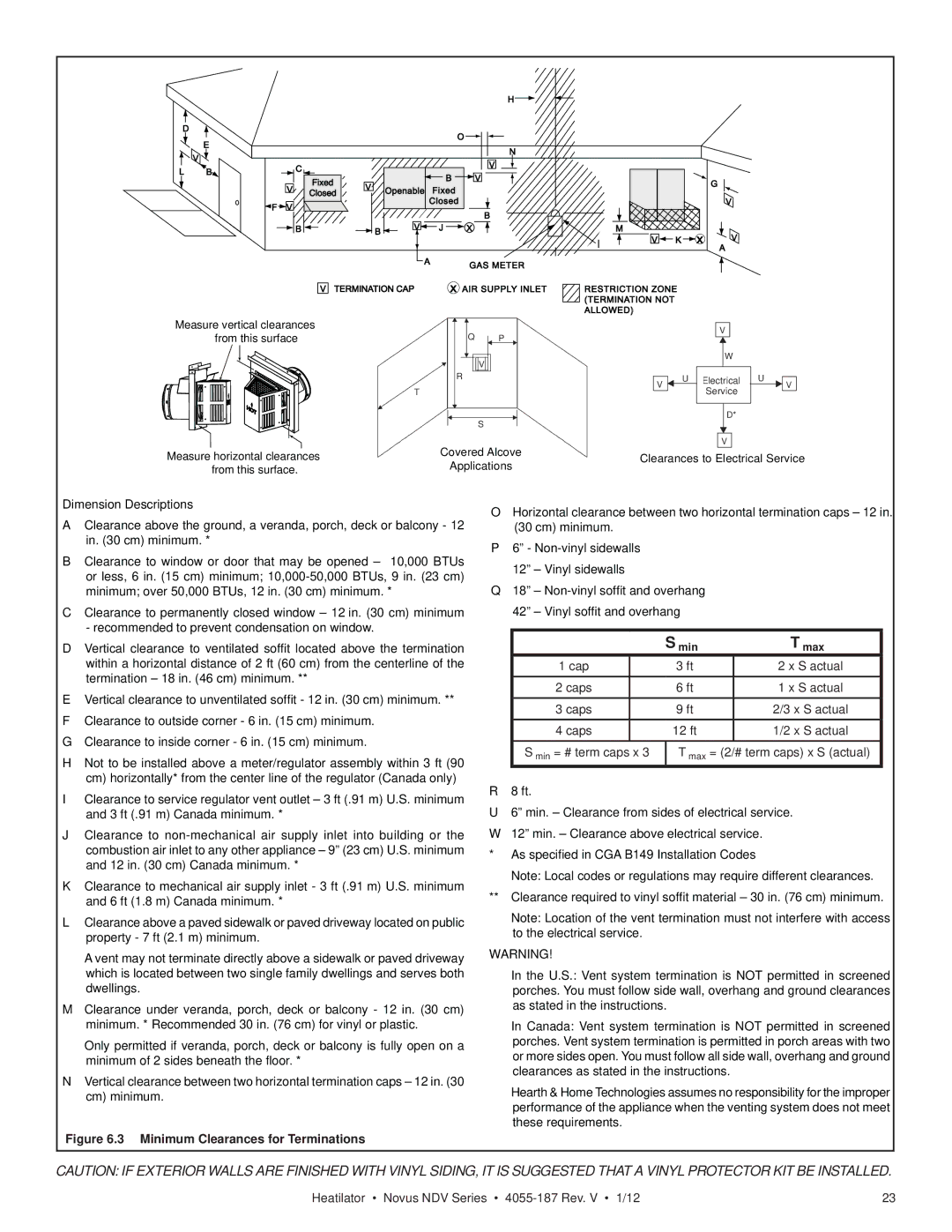
Dimension Descriptions

AClearance above the ground, a veranda, porch, deck or balcony - 12 in. (30 cm) minimum. *

BClearance to window or door that may be opened – 10,000 BTUs or less, 6 in. (15 cm) minimum; 10,000-50,000 BTUs, 9 in. (23 cm) minimum; over 50,000 BTUs, 12 in. (30 cm) minimum. *

CClearance to permanently closed window – 12 in. (30 cm) minimum - recommended to prevent condensation on window.

DVertical clearance to ventilated soffit located above the termination within a horizontal distance of 2 ft (60 cm) from the centerline of the termination – 18 in. (46 cm) minimum. **

EVertical clearance to unventilated soffit - 12 in. (30 cm) minimum. **

FClearance to outside corner - 6 in. (15 cm) minimum.

GClearance to inside corner - 6 in. (15 cm) minimum.

HNot to be installed above a meter/regulator assembly within 3 ft (90 cm) horizontally* from the center line of the regulator (Canada only)

IClearance to service regulator vent outlet – 3 ft (.91 m) U.S. minimum and 3 ft (.91 m) Canada minimum. *

JClearance to non-mechanical air supply inlet into building or the combustion air inlet to any other appliance – 9” (23 cm) U.S. minimum and 12 in. (30 cm) Canada minimum. *

KClearance to mechanical air supply inlet - 3 ft (.91 m) U.S. minimum and 6 ft (1.8 m) Canada minimum. *

LClearance above a paved sidewalk or paved driveway located on public property - 7 ft (2.1 m) minimum.

A vent may not terminate directly above a sidewalk or paved driveway which is located between two single family dwellings and serves both dwellings.

MClearance under veranda, porch, deck or balcony - 12 in. (30 cm) minimum. * Recommended 30 in. (76 cm) for vinyl or plastic.

Only permitted if veranda, porch, deck or balcony is fully open on a minimum of 2 sides beneath the floor. *

NVertical clearance between two horizontal termination caps – 12 in. (30 cm) minimum.

Figure 6.3 Minimum Clearances for Terminations

OHorizontal clearance between two horizontal termination caps – 12 in. (30 cm) minimum.

P6” - Non-vinyl sidewalls 12” – Vinyl sidewalls

Q18” – Non-vinyl soffit and overhang 42” – Vinyl soffit and overhang


S min

T max

1 cap


3 ft

2 x S actual

2 caps


6 ft

1 x S actual

3 caps


9 ft

2/3 x S actual

4 caps


12 ft

1/2 x S actual

S min = # term caps x 3

T max = (2/# term caps) x S (actual)

R 8 ft.

U6” min. – Clearance from sides of electrical service. W 12” min. – Clearance above electrical service.

* As specified in CGA B149 Installation Codes

Note: Local codes or regulations may require different clearances. ** Clearance required to vinyl soffit material – 30 in. (76 cm) minimum.

Note: Location of the vent termination must not interfere with access to the electrical service.

WARNING!

In the U.S.: Vent system termination is NOT permitted in screened porches. You must follow side wall, overhang and ground clearances as stated in the instructions.

In Canada: Vent system termination is NOT permitted in screened porches. Vent system termination is permitted in porch areas with two or more sides open. You must follow all side wall, overhang and ground clearances as stated in the instructions.

Hearth & Home Technologies assumes no responsibility for the improper performance of the appliance when the venting system does not meet these requirements.

CAUTION: IF EXTERIOR WALLS ARE FINISHED WITH VINYL SIDING, IT IS SUGGESTED THAT A VINYL PROTECTOR KIT BE INSTALLED.

Heatilator • Novus NDV Series • 4055-187 Rev. V • 1/12

23

Page 23
Image 23
Hearth and Home Technologies 4055-187 owner manual Minimum Clearances for Terminations

4055-187 specifications

Hearth and Home Technologies (HHT) has long been a leader in the fireplace and home heating sector, providing innovative solutions that enhance comfort and aesthetics in homes across the globe. One of their standout offerings is the HHT 4055-187 model, which showcases a harmonious blend of functionality and design, making it a highly sought-after option for both new constructions and remodels.

The HHT 4055-187 is a gas fireplace, revered for its efficiency and convenience. One of its main features is the direct vent technology, which allows for safe and efficient venting of combustion gases directly outside. This not only improves the air quality indoors but also enables the fireplace to be installed in virtually any location without the need for a traditional chimney. With its aesthetic appeal, the 4055-187 boasts a customizable design, allowing users to choose from various media options, including pebbles or logs, to personalize their fireplace experience.

In terms of performance, the HHT 4055-187 is engineered for efficiency. It provides a considerable heat output, ensuring rooms are warmed quickly and effectively. The fireplace includes features such as adjustable flame height and temperature control, allowing users to customize their heating experience based on their comfort preferences. The inclusion of an intuitive remote control system further enhances user convenience, enabling effortless adjustments from across the room.

The model's LED lighting also adds a contemporary touch, creating an inviting ambiance even when the fireplace is not in use. The HHT 4055-187 is built with impressive durability, utilizing high-quality materials designed to withstand the rigors of regular use while maintaining its sleek appearance.

Safety features are paramount, making this model an ideal choice for families. The unit includes automatic shut-off mechanisms and tempered glass to protect against accidental contact. Additionally, its innovative design minimizes the risk of accidental fuel leaks, ensuring peace of mind for homeowners.

In summary, the Hearth and Home Technologies 4055-187 is more than just a heating appliance; it is a centerpiece that combines modern technology, aesthetic flexibility, and safety for a truly impressive fireplace experience. Whether you are seeking warmth on a chilly evening or looking to enhance your living space with a focal point, the HHT 4055-187 stands out as a reliable and stylish choice.