Canadian Equipment Requirements
This digital apparatus does not exceed the (Class A/Class B)* limits for radio noise emissions from digital apparatus set out in the Radio Interference Regulations of the Canadian Department of Communications. Le present appareil numerique n’emet pas de bruits radioelectriques depassant les limites applicables aux appareils numeriques (de la class A/de la class B)* prescrites dans le Reglement sur le brouillage radioelectrique edicte par le ministere des Communications du Canada.
This device complies with
(1)this device may not cause interference, and (2) this device must accept any interference, including interference that may cause undesired operation of the device.
INSTALLATION INSTRUCTIONS
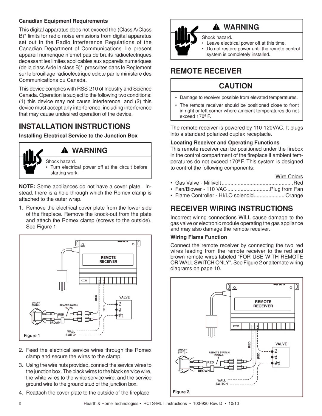
Installing Electrical Service to the Junction Box
![]() WARNING
WARNING
Shock hazard.
•Turn electrical power off at the circuit before starting work.
NOTE: Some appliances do not have a cover plate. In- stead, there is a hole through which the Romex clamp is attached to the outer wrap.
1.Remove the electrical cover plate from the lower side of the fireplace. Remove the
|
| REMOTE |
| |
|
| RECEIVER |
| |
|
| RED | VALVE | |
|
| TH | ||
ON/OFF |
|
| ||
SWITCH | REMOTE SWITCH | RED | ||
| ||||
| PIGTAIL | TP | ||
|
| |||
| RED |
| TP TH | |
|
|
| ||
| BROWN |
|
| |
Figure 1 | WALL |
|
| |
SWITCH |
|
|
2.Feed the electrical service wires through the Romex clamp and secure the wires to the clamp.
3.Using the wire nuts provided, connect the service wires to the junction box. The black wires to the black service wire, the white wires to the white service wire, and the service ground wire to the ground stud of the junction box.
4.Reattach the cover plate to the outside of the fireplace.
![]() WARNING
WARNING
Shock hazard.
•Leave electrical power off at this time.
•Do not restore power until the remote control system is completely installed.
REMOTE RECEIVER
CAUTION
•Damage to receiver possible from elevated temperatures.
•The remote receiver should be positioned close to front in right or left corner where ambient temperatures do not exceed 170º F.
The remote receiver is powered by
Locating Receiver and Operating Functions
This remote receiver can be positioned under the firebox in the control compartment of the fireplace if ambient tem- peratures do not exceed 1700 F. This system is designed to control the following components:
|
| Wire Colors |
• | Gas Valve - Millivolt | Red |
• Fan/Blower - 110 VAC | Plug from Fan | |
• | Flame Controller - HI/LO solenoid | Orange |
RECEIVER WIRING INSTRUCTIONS
Incorrect wiring connections WILL cause damage to the gas valve or electronic module operating the gas appliance and may also damage the remote receiver.
Wiring Flame Function
Connect the remote receiver by connecting the two red wires leading from the remote receiver to the red and brown remote wires labeled “FOR USE WITH REMOTE OR WALL SWITCH ONLY”. See Figure 2 or alternate wiring diagrams on page 10.
|
| REMOTE |
| |
|
| RECEIVER |
| |
|
| RED | VALVE | |
ON/OFF |
| TH | ||
|
| |||
SWITCH | REMOTE SWITCH | RED | ||
| ||||
| PIGTAIL | TP | ||
|
| |||
| RED |
| TP TH | |
|
|
| ||
| BROWN |
|
| |
| WALL |
|
| |
| SWITCH |
|
| |
Figure 2. |
|
|
|
2 | Hearth & Home Technologies • |