Alternative Wiring for units with a wall switch
Disconnect the wall switch wire from the TH terminal on the valve and connect this wire to male connector supplied on the receiver. Connect remaining female connector from receiver to the TH terminal on the valve.
Adding Optional Fan/Blower
Plug
(Receptacle on back) ![]()
![]()
LEARN110/120 VAC, 3A
REMOTE |
|
|
|
|
|
|
RECEIVER | Line cord | |||||
| from fan | |||||
Figure 3. Adding Fan/Blower
NOTE: All steps required for installation of the flame controller MUST be done by a qualified gas service technician.
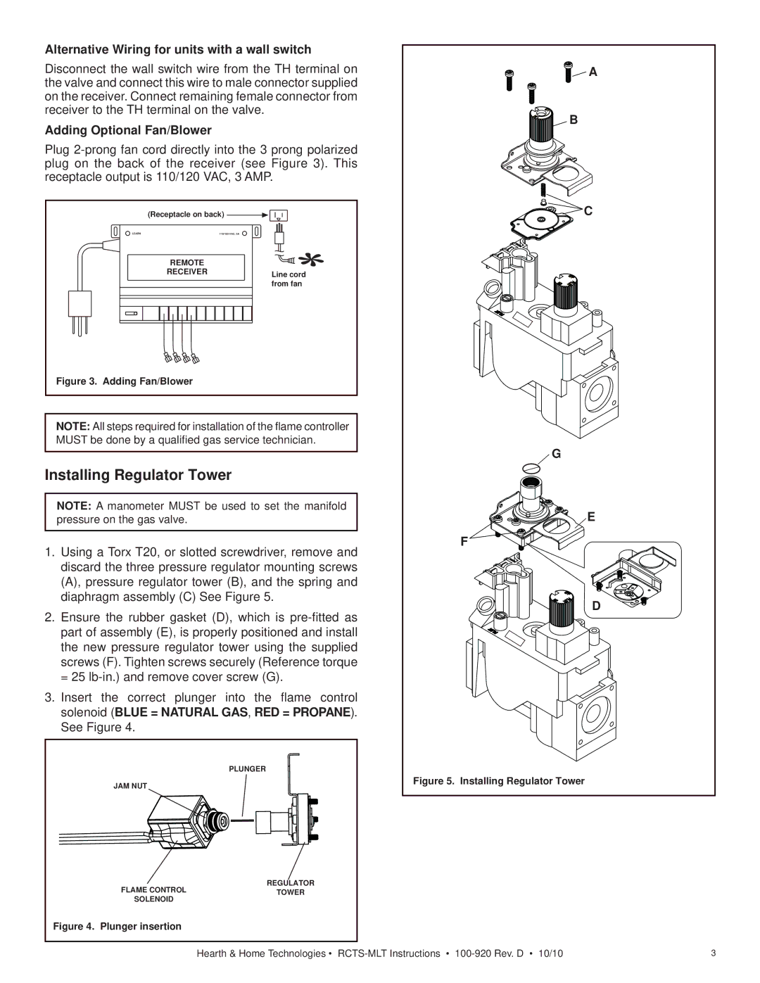
Installing Regulator Tower
NOTE: A manometer MUST be used to set the manifold pressure on the gas valve.
1.Using a Torx T20, or slotted screwdriver, remove and discard the three pressure regulator mounting screws (A), pressure regulator tower (B), and the spring and diaphragm assembly (C) See Figure 5.
2.Ensure the rubber gasket (D), which is
3.Insert the correct plunger into the flame control solenoid (BLUE = NATURAL GAS, RED = PROPANE). See Figure 4.
|
| PLUNGER |
| JAM NUT |
|
| FLAME CONTROL | REGULATOR |
| TOWER | |
| SOLENOID |
|
Figure 4. | Plunger insertion |
|
![]()
![]()
![]() A
A
![]()
![]()
![]()
![]()
![]()
![]()
![]()
![]()
![]()
![]() B
B
![]()
![]()
![]()
![]()
![]()
![]()
![]() C
C
G
E
F ![]()
![]()
![]()
![]()
![]()
![]()
![]()
![]()
![]()
![]()
![]()
D
Figure 5. Installing Regulator Tower
Hearth & Home Technologies • | 3 |