Adjusting “Low Flame” setting (LP ONLY)
1.Using a 5/16 in. slotted screwdriver turn brass screw inside regulator tower two complete rotations clock- wise. See Figure 6.
Figure 6.
2.Loosen outlet pressure tap and install a manometer.
3.Light the fireplace as directed in the Owner’s Manual.
4.Continue to adjust the LP “Low Flame” by turning brass screw clockwise to increase pressure and coun- terclockwise to reduce pressure. Adjust until the low pressure reading on the manometer to 6.3 in. w.c.
NOTE: Low Pressure reading must be adjusted to 3.6 in.
w.c. for these models:
5. Proceed to installing Flame Control Solenoid.
![]() WARNING
WARNING
EXPLOSION RISK!
•Adjust lowpoint setting BEFORE installing flame control solenoid on LP units.
NOTE: A manometer MUST be used to set the manifold pressure on the gas valve.
Installing the Flame Control Solenoid and Wiring the Flame Controller (NG & LP)
1.Ensure the Flame Control Solenoid is not attached to the remote control receiver box.
2.Loosen outlet pressure tap and install a manometer.
3.Install Flame Control Solenoid by turning it into the regula- tor tower five complete rotations clockwise. See Figure 7.
JAM NUT
Figure 7.
4.Light the fireplace as directed in the Owner’s Manual.
5.Adjust “High Flame” by turning solenoid clockwise to increase pressure and counterclockwise to reduce pressure. Adjust until the reading on the manometer is 3.5 inches w.c. for natural gas and 10 in w.c. for LP.
6.Tighten jam nut (Figure 4 and Figure 7) to the face of the regulator tower body.
7.Turn the main gas knob on the gas valve OFF.
8.Remove the manometer from the pressure tap and tighten the pressure tap closed.
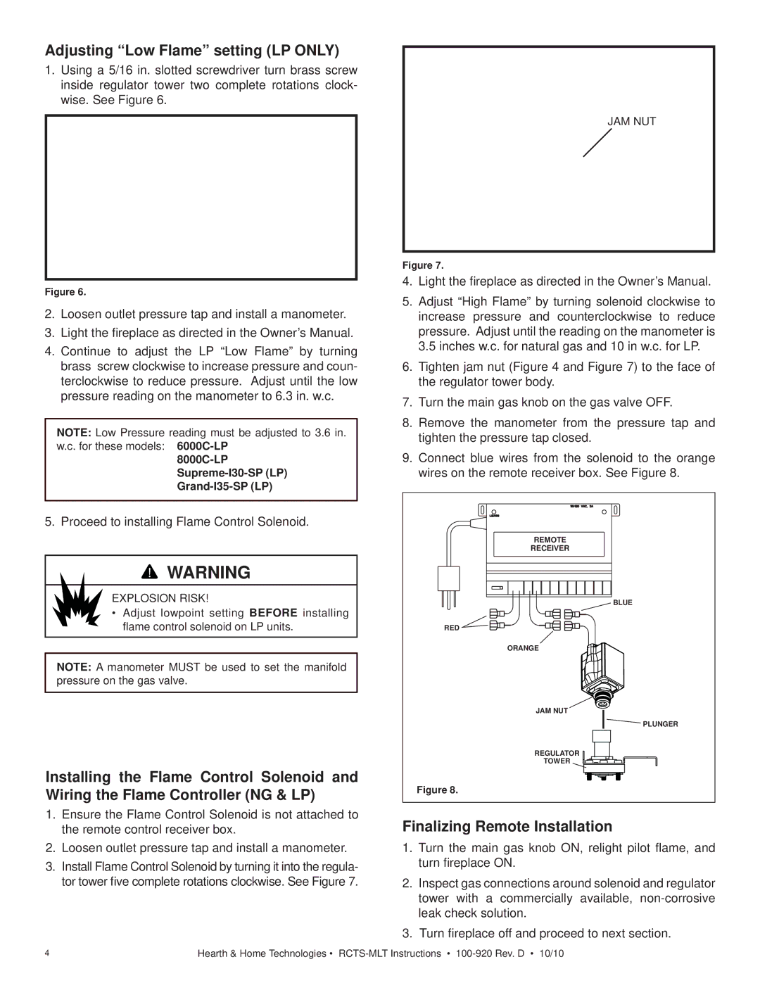
9.Connect blue wires from the solenoid to the orange wires on the remote receiver box. See Figure 8.
REMOTE |
RECEIVER |
BLUE
RED |
ORANGE
JAM NUT
![]() PLUNGER
PLUNGER
REGULATOR
TOWER
Figure 8.
Finalizing Remote Installation
1.Turn the main gas knob ON, relight pilot flame, and turn fireplace ON.
2.Inspect gas connections around solenoid and regulator tower with a commercially available,
3.Turn fireplace off and proceed to next section.
4 | Hearth & Home Technologies • |