A. Unpacking the Unit
WARNING! Do NOT use this appliance if any part has been under water. Immediately call a qualified service techni- cian to inspect and to replace any part of the electrical system if necessary.
Carefully remove packaging from the unit. The front screen is held in place with four Phillips head screws. To remove the screen, extract the screws. Grasp the screen frame and pull out.
B. Locating Your Electric Fireplace
Your new electric fireplace may be installed virtually anywhere in your home. However, when choosing a location ensure that the general instructions are followed. For best results, install out of direct sunlight.
C. Framing
•Choose a fireplace location and frame as shown in Figure 2.1.
•Provide a properly gounded, 120 volt, 60 Hz, 15 AMP circuit as shown in Figure 2.1.
D. Electrical Specifications
Voltage . . . . . . . . . . . . . . . . . . . . . . 120 V AC, 60 Hz
Total Amps . . . . . . . . . . . . . . . . . . . . . . . . . .9.6 AMP
Total Watts . . . . . . . . . . . . . . . . . . . . . . . 1050 Watts
Heater Rating: . . . . . . . . . . . .1000 Watts/3415 BTU
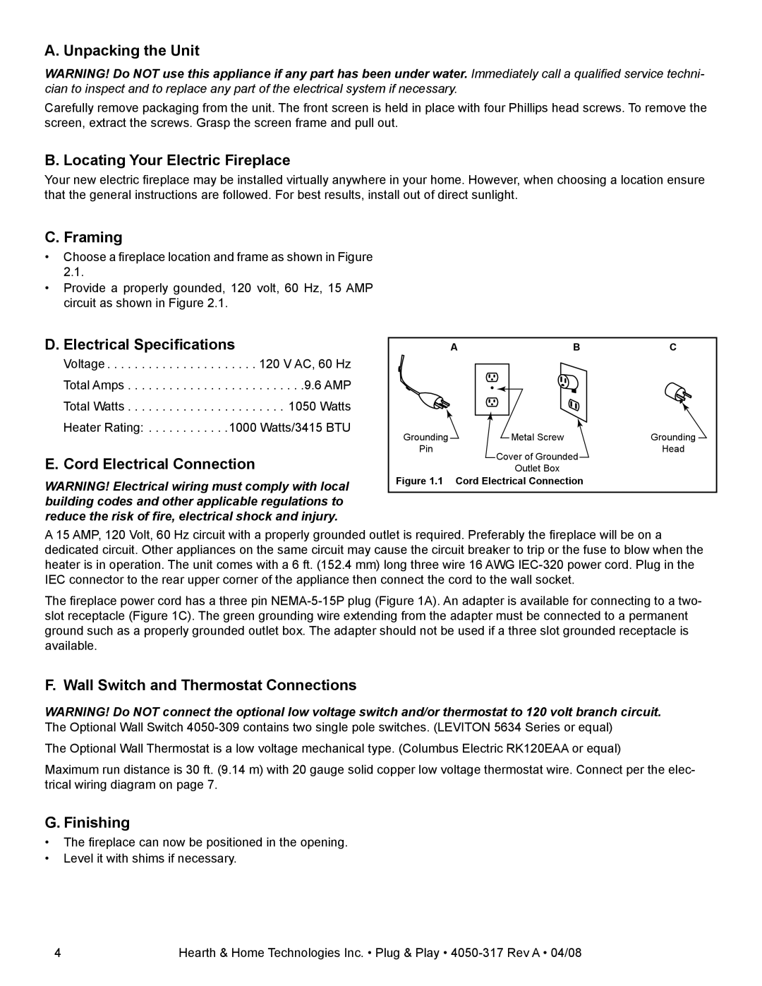
E. Cord Electrical Connection
WARNING! Electrical wiring must comply with local building codes and other applicable regulations to reduce the risk of fire, electrical shock and injury.
ABC
Grounding | Metal Screw | Grounding |
Pin | Cover of Grounded | Head |
|
| |
| Outlet Box |
|
Figure 1.1 Cord Electrical Connection
A 15 AMP, 120 Volt, 60 Hz circuit with a properly grounded outlet is required. Preferably the fireplace will be on a dedicated circuit. Other appliances on the same circuit may cause the circuit breaker to trip or the fuse to blow when the heater is in operation. The unit comes with a 6 ft. (152.4 mm) long three wire 16 AWG
The fireplace power cord has a three pin
F. Wall Switch and Thermostat Connections
WARNING! Do NOT connect the optional low voltage switch and/or thermostat to 120 volt branch circuit.
The Optional Wall Switch
Maximum run distance is 30 ft. (9.14 m) with 20 gauge solid copper low voltage thermostat wire. Connect per the elec- trical wiring diagram on page 7.
G. Finishing
•The fireplace can now be positioned in the opening.
•Level it with shims if necessary.
4 | Hearth & Home Technologies Inc. • Plug & Play • |