Step 4. Installing the Vent System
A. Vent System Approvals
Model 8000TVD is approved to use
These models may also use single wall rigid or flexible gas vent IF and ONLY IF the vent system is installed within
For
The flame and ember appearance may vary based on the type of fuel burned and the venting configuration used.
B. System Components.
Vent System Configuration
RISE TO RUN RATIO = 2:1
MAXIMUM TOTAL HORIZONTAL RUN = 15 FT.
MINIMUM TOTAL VERTICAL RISE = 9 FT.
MAXIMUM NO. Of ELBOWS: 2 - 90o or 4 - 45o
Plan and install the vent system using the parameters shown above.
!WARNING: YOU MUST NOT EXCEED THESE PARAMETERS.
Connect a
NOTE: It is always better to first attach a straight section of vent to the unit before attaching an elbow. Avoid using elbows in the vent system if possible.
A
A minimum of 9 foot vertical rise ending in a listed termination cap is required for the unit.
Continue to add vent components, until the vent run is completed.
WARNING: YOU MUST NOT EXCEED A TOTAL ! MAXIMUM HORIZONTAL RUN OF 15 FEET FOR
THE ENTIRE VENT SYSTEM.
LISTED |
TERMINATION CAP |
LISTED |
GAS VENT |
CONSTRUCTION |
VENT |
H |
V |
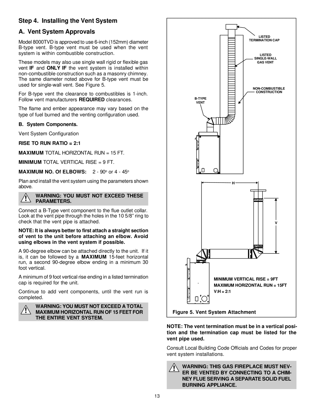
MINIMUM VERTICAL RISE = 9FT
MAXIMUM HORIZONTAL RUN = 15FT
V:H = 2:1
Figure 5. Vent System Attachment
NOTE: The vent termination must be in a vertical posi- tion and the termination cap must be listed for the vent pipe used.
Consult Local Building Code Officials and Codes for proper vent system installations.
!WARNING: THIS GAS FIREPLACE MUST NEV- ER BE VENTED BY CONNECTING TO A CHIM- NEY FLUE SERVING A SEPARATE SOLID FUEL BURNING APPLIANCE.
13