C. Bedroom Installation in Canada
This model MUST NOT be vented into a vent system in- stalled exterior to a building. The part of the vent system above the roof line can be exterior to the building.
D.Vent Termination
!WARNING: MAJOR U.S. BUILDING CODES SPECIFY MINIMUM CHIMNEY AND/OR VENT HEIGHT ABOVE THE ROOF TOP. THESE MIN- IMUM HEIGHTS ARE NECESSARY IN THE IN- TEREST OF SAFETY. FIGURE 6 AND TABLE SHOW MINIMUM HEIGHTS, PROVIDED THE TERMINATION CAP IS AT LEAST
Step 5. Positioning, Leveling, and Securing the Fireplace
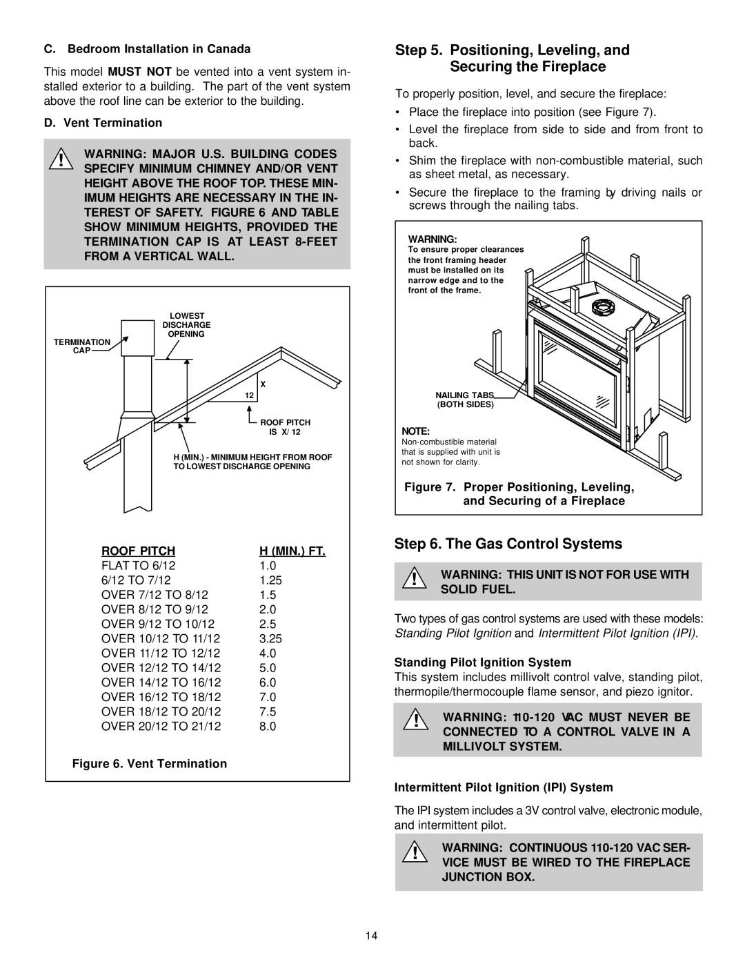
To properly position, level, and secure the fireplace:
•Place the fireplace into position (see Figure 7).
•Level the fireplace from side to side and from front to back.
•Shim the fireplace with
•Secure the fireplace to the framing by driving nails or screws through the nailing tabs.
WARNING:
To ensure proper clearances the front framing header must be installed on its narrow edge and to the front of the frame.
TERMINATION
CAP
LOWEST
DISCHARGE
OPENING
X
12
![]() ROOF PITCH
ROOF PITCH
IS X/ 12
H (MIN.) - MINIMUM HEIGHT FROM ROOF TO LOWEST DISCHARGE OPENING
NAILING TABS (BOTH SIDES)
NOTE:
Figure 7. Proper Positioning, Leveling, and Securing of a Fireplace
ROOF PITCH | H (MIN.) FT. |
FLAT TO 6/12 | 1.0 |
6/12 TO 7/12 | 1.25 |
OVER 7/12 TO 8/12 | 1.5 |
OVER 8/12 TO 9/12 | 2.0 |
OVER 9/12 TO 10/12 | 2.5 |
OVER 10/12 TO 11/12 | 3.25 |
OVER 11/12 TO 12/12 | 4.0 |
OVER 12/12 TO 14/12 | 5.0 |
OVER 14/12 TO 16/12 | 6.0 |
OVER 16/12 TO 18/12 | 7.0 |
OVER 18/12 TO 20/12 | 7.5 |
OVER 20/12 TO 21/12 | 8.0 |
Figure 6. Vent Termination
Step 6. The Gas Control Systems
!WARNING: THIS UNIT IS NOT FOR USE WITH SOLID FUEL.
Two types of gas control systems are used with these models: Standing Pilot Ignition and Intermittent Pilot Ignition (IPI).
Standing Pilot Ignition System
This system includes millivolt control valve, standing pilot, thermopile/thermocouple flame sensor, and piezo ignitor.
!WARNING:
Intermittent Pilot Ignition (IPI) System
The IPI system includes a 3V control valve, electronic module, and intermittent pilot.
!WARNING: CONTINUOUS
VICE MUST BE WIRED TO THE FIREPLACE JUNCTION BOX.
14