| BLACK L1 | BLACK L2 |
|
| |
|
| REMOTE SWITCH |
GAS VALVE |
| PIGTAIL |
|
| |
|
| ON |
|
| OFF |
| WHITE T2 | ON/OFF SWITCH |
|
| |
| RED T1 |
|
| THERMOPILE | |
THERMOCOUPLE | BLACK S1 | OPTIONAL WALL SWITCH, |
| ||
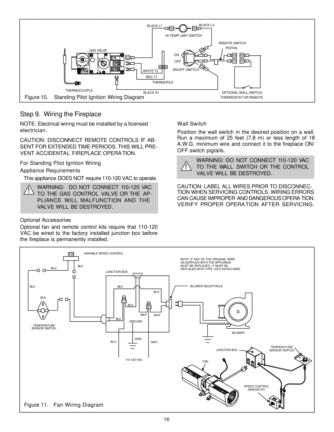
Figure 10. Standing Pilot Ignition Wiring Diagram | THERMOSTAT OR REMOTE | |
Step 9. Wiring the Fireplace
NOTE: Electrical wiring must be installed by a licensed electrician.
CAUTION: DISCONNECT REMOTE CONTROLS IF AB- SENT FOR EXTENDED TIME PERIODS. THIS WILL PRE- VENT ACCIDENTAL FIREPLACE OPERATION.
For Standing Pilot Ignition Wiring
Appliance Requirements
• This appliance DOES NOT require
Wall Switch
Position the wall switch in the desired position on a wall. Run a maximum of 25 feet (7.8 m) or less length of 18 A.W.G. minimum wire and connect it to the fireplace ON/ OFF switch pigtails.
WARNING: DO NOT CONNECT
!TO THE WALL SWITCH OR THE CONTROL VALVE WILL BE DESTROYED.
WARNING: DO NOT CONNECT
!TO THE GAS CONTROL VALVE OR THE AP- PLIANCE WILL MALFUNCTION AND THE VALVE WILL BE DESTROYED.
Optional Accessories
Optional fan and remote control kits require that
CAUTION: LABEL ALL WIRES PRIOR TO DISCONNEC- TION WHEN SERVICING CONTROLS. WIRING ERRORS CAN CAUSE IMPROPER AND DANGEROUS OPERATION. VERIFY PROPER OPERATION AFTER SERVICING.
BLK
BLK
BLK
TEMPERATURE SENSOR SWITCH
VARIABLE SPEED CONTROL
BLK
JUNCTION BOX
BLK |
|
| BLK |
BLK |
|
WHT | WHT |
BLK |
|
GROUND |
|
GRN |
|
BLK | WHT |
|
NOTE: IF ANY OF THE ORIGINAL WIRE AS SUPPLIED WITH THE APPLIANCE MUST BE REPLACED, IT MUST BE REPLACED WITH TYPE 105 OC RATED WIRE.
BLOWER RECEPTACLE
BLOWER
JUNCTION BOX
FAN
TEMPERATURE SENSOR SWITCH
SPEED CONTROL
(RHEOSTAT)
Figure 11. Fan Wiring Diagram
16