C. Assembling Chimney Sections

Warning! Risk of Fire! Do NOT install substitute or damaged chimney components.

Use only those components described in this manual.

Substitute or damaged chimney components could impair safe operation and cause overheating and fire.

Support the pipe during construction and check to be sure inadvertent loading has not dislodged the chimney section from the fireplace or at any chimney joint.

Attach a straight chimney section or an offset to the top of the fireplace.

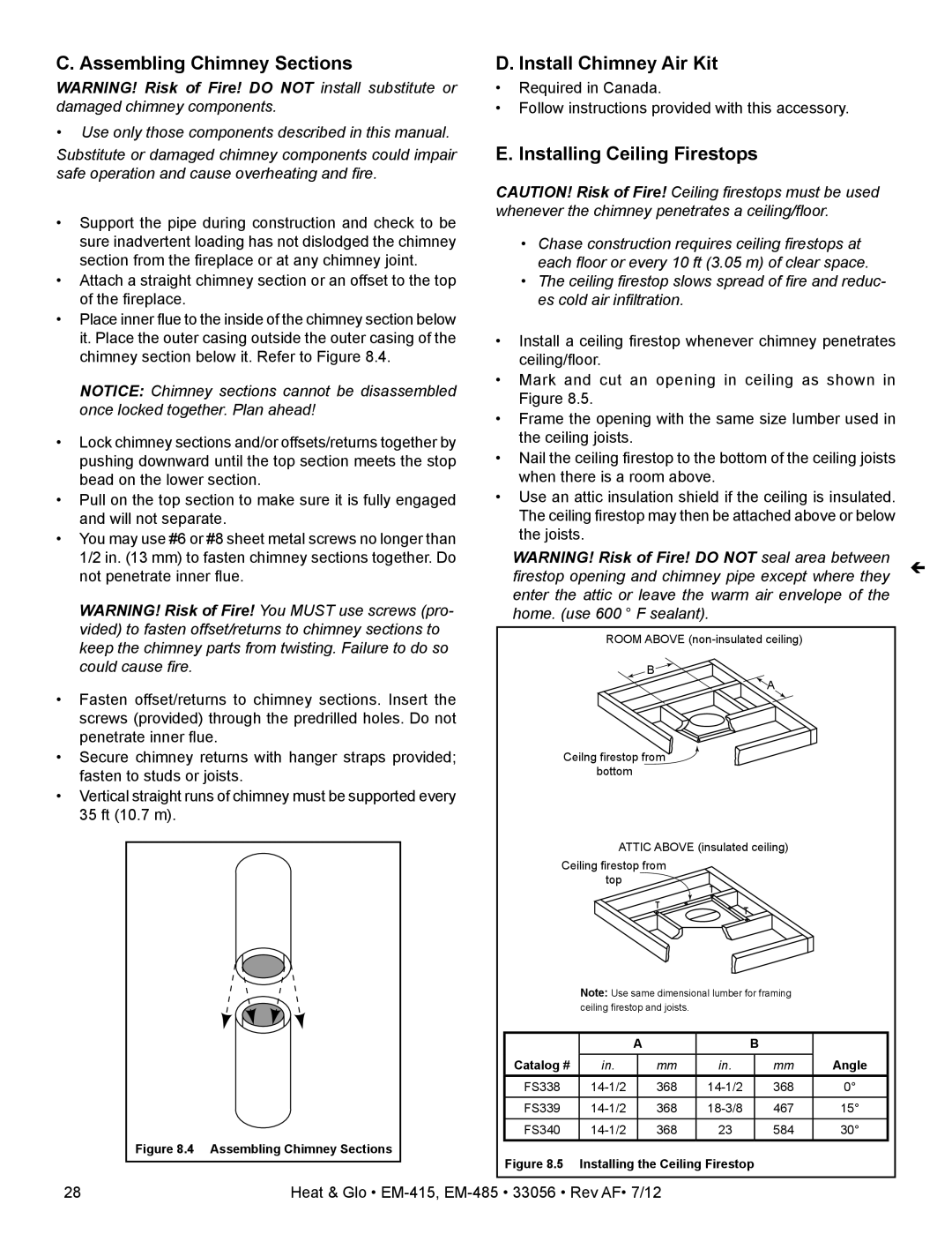
Place inner flue to the inside of the chimney section below it. Place the outer casing outside the outer casing of the chimney section below it. Refer to Figure 8.4.

NoTICE: Chimney sections cannot be disassembled once locked together. Plan ahead!

Lock chimney sections and/or offsets/returns together by pushing downward until the top section meets the stop bead on the lower section.

Pull on the top section to make sure it is fully engaged and will not separate.

You may use #6 or #8 sheet metal screws no longer than 1/2 in. (13 mm) to fasten chimney sections together. Do not penetrate inner flue.

Warning! Risk of Fire! You MUST use screws (pro- vided) to fasten offset/returns to chimney sections to keep the chimney parts from twisting. Failure to do so could cause fire.

Fasten offset/returns to chimney sections. Insert the screws (provided) through the predrilled holes. Do not penetrate inner flue.

Secure chimney returns with hanger straps provided; fasten to studs or joists.

Vertical straight runs of chimney must be supported every 35 ft (10.7 m).

Figure 8.4 Assembling Chimney Sections

D. Install Chimney Air Kit

Required in Canada.

Follow instructions provided with this accessory.

E. Installing Ceiling Firestops

Caution! Risk of Fire! Ceiling firestops must be used whenever the chimney penetrates a ceiling/floor.

Chase construction requires ceiling firestops at each floor or every 10 ft (3.05 m) of clear space.

The ceiling firestop slows spread of fire and reduc- es cold air infiltration.

Install a ceiling firestop whenever chimney penetrates ceiling/floor.

Mark and cut an opening in ceiling as shown in Figure 8.5.

Frame the opening with the same size lumber used in the ceiling joists.

Nail the ceiling firestop to the bottom of the ceiling joists when there is a room above.

Use an attic insulation shield if the ceiling is insulated. The ceiling firestop may then be attached above or below the joists.

Warning! Risk of Fire! Do NOT seal area between

firestop opening and chimney pipe except where they


enter the attic or leave the warm air envelope of the


home. (use 600 ° F sealant).


ROOM ABOVE (non-insulated ceiling)

B

A

Ceilng firestop from bottom

ATTIC ABOVE (insulated ceiling)

Ceiling firestop from

top

Note: Use same dimensional lumber for framing ceiling firestop and joists.


A


B


Catalog #

in.


mm

in.


mm

Angle

FS338

14-1/2


368

14-1/2


368

FS339

14-1/2


368

18-3/8


467

15°


FS340

14-1/2


368

23


584

30°

Figure 8.5 Installing the Ceiling Firestop

28

Heat & Glo • EM-415, EM-485 • 33056 • Rev AF• 7/12

Page 28
Image 28
Heat & Glo LifeStyle EM-415 - 36 Assembling Chimney Sections, Install Chimney Air Kit, Installing Ceiling Firestops

EM-485T - 42, EM-415 - 36 specifications

Heat & Glo has established itself as a leader in innovative fireplace solutions, and the LifeStyle series, particularly the EM-415 and EM-485T models, showcases the brand's commitment to quality, efficiency, and design flexibility. These gas fireplaces are designed to seamlessly blend into any living space, providing not just warmth but also a stylish focal point.

The EM-415, with its 36-inch firebox, and the EM-485T, featuring a generous 42-inch firebox, deliver a stunning visual experience. Both models boast a contemporary design that enhances the aesthetics of modern homes. The clean, linear appearance is complemented by a large viewing area, allowing for an unobstructed view of the flames.

In terms of technology, Heat & Glo incorporates advanced features such as Intellifire™ Ignition System, which allows for reliable and safe start-up while ensuring energy efficiency. This system also includes the option for remote control operation, providing added convenience for users. The fireplaces can be easily adjusted to suit individual comfort levels, with variable flame settings that allow for customizable heat output.

Additionally, both models utilize the latest in heat management technology. The Heat & Glo LifeStyle series is designed with excellent insulation, promoting better heat retention and minimizing heat loss. This not only enhances the efficiency of the fireplace but also contributes to overall energy savings.

Safety is paramount in the design of the EM-415 and EM-485T. They are equipped with standard safety features such as an automatic shut-off system, ensuring peace of mind while the fireplace is in use.

Moreover, the versatility of these models is highlighted by their ability to be installed in various settings, including walls and corners. The option for different media, such as glass or stone, allows homeowners to personalize their fireplace, making it a perfect fit for any decor style.

Overall, the Heat & Glo LifeStyle EM-415 and EM-485T gas fireplaces represent a fusion of aesthetics, technology, and safety, making them an ideal choice for anyone looking to enhance the comfort and style of their home. With their range of features and design options, these models are sure to create a warm and inviting atmosphere for years to come.