Owner’s Manual | Glass Panel Heater | Heat Controller |
|
|
|
FIXED WALL MOUNT OPTION–INSTALLATION
1.The wall brackets supplied with the heater must be used for the wall mount option
2.The heater should be positioned observing the minimum clearances stated around the heater:
| MINIMUM CLEARANCES (SEE FIG 1) : | |
| From top surface of heater | 18” (450mm) |
| From side of heater | 10” (250mm) |
| From bottom of heater | 6” (150mm) |
Do not locate the heater where a draft may affect the ambient temperature readings, and thus the controll setting.
3.First remove the wall bracket from the rear housing of the heater. Unscrew the (2) screws located on the top of the two vertical bars of the wall bracket (see Step1 on page 3).
4.Pull out the top of the bar by pressing firmly on both upper tabs slotted into the rear housing (Step 2).
5.Slide the wall bracket down to remove it from the rear housing (Step 3).
6.Fix the wall bracket securely to the wall through the (4) screw holes provided. Use wall anchors if necessary (not provided).
7. Hold the heater in the upright (vertical) position. and position the top of heater against the wall bracket. Push the bottom slots on the heater’s back enclosure onto bottom tabs on the vertical bracket bars. Pull up on the heater to seat the heater onto the bracket.
8.Push the heater toward the top of the bracket’s vertical bars, firmly seating the bracket tabs into the top slots on the back of the heater enclosure. Tighten the (2) screws on the top of the bracket’s vertical bars to lock the heater to the mounting bracket (Step 4).
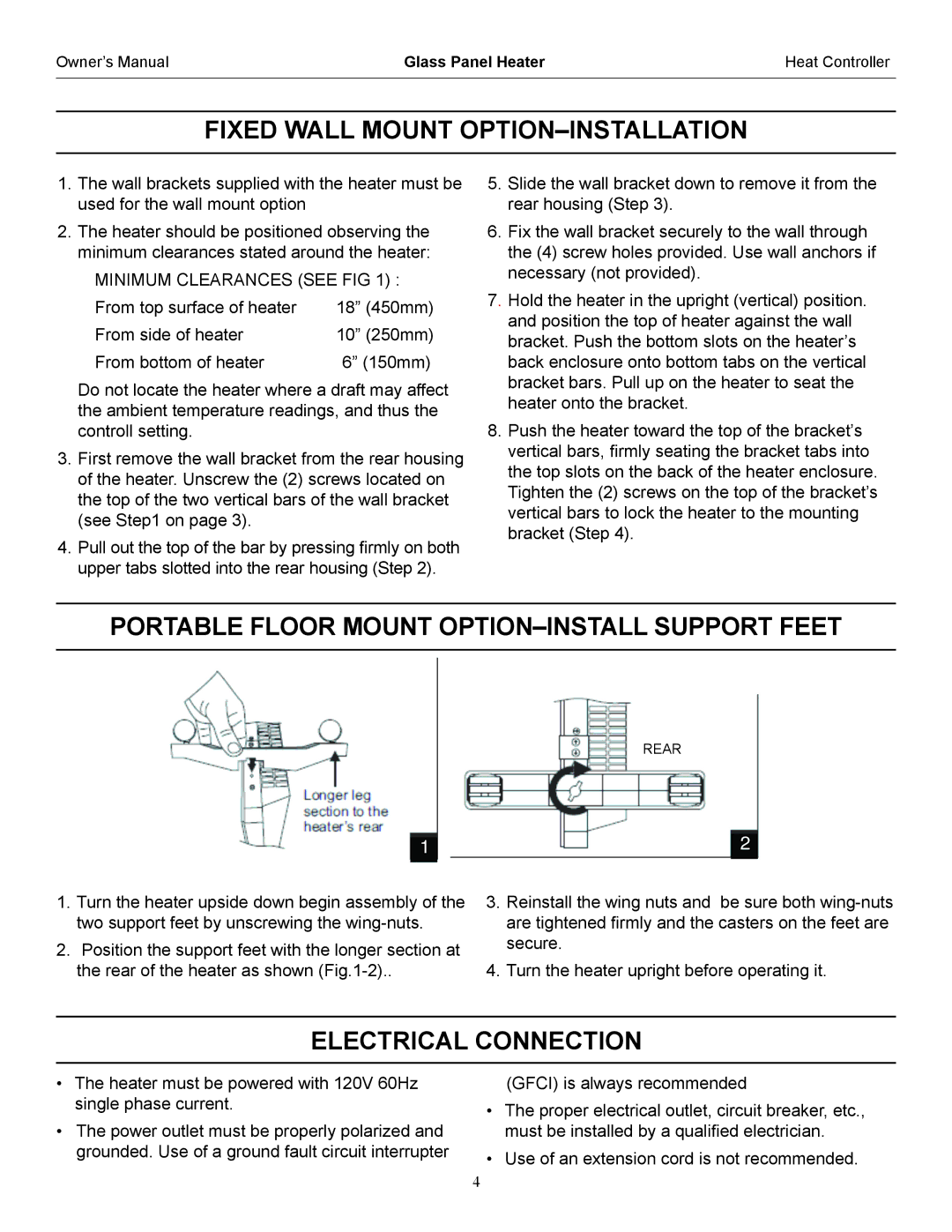
PORTABLE FLOOR MOUNT OPTION–INSTALL SUPPORT FEET
REAR
1.Turn the heater upside down begin assembly of the two support feet by unscrewing the
2.Position the support feet with the longer section at the rear of the heater as shown
3.Reinstall the wing nuts and be sure both
4.Turn the heater upright before operating it.
ELECTRICAL CONNECTION
•The heater must be powered with 120V 60Hz single phase current.
•The power outlet must be properly polarized and grounded. Use of a ground fault circuit interrupter
(GFCI) is always recommended
•The proper electrical outlet, circuit breaker, etc., must be installed by a qualified electrician.
•Use of an extension cord is not recommended.
4