Manuals
/
Heat Controller
/
Household Appliance
/
Heating System
Heat Controller
TGC048C-3K-135, TGC060C-4K-135, TGC048C-1K-135
manual
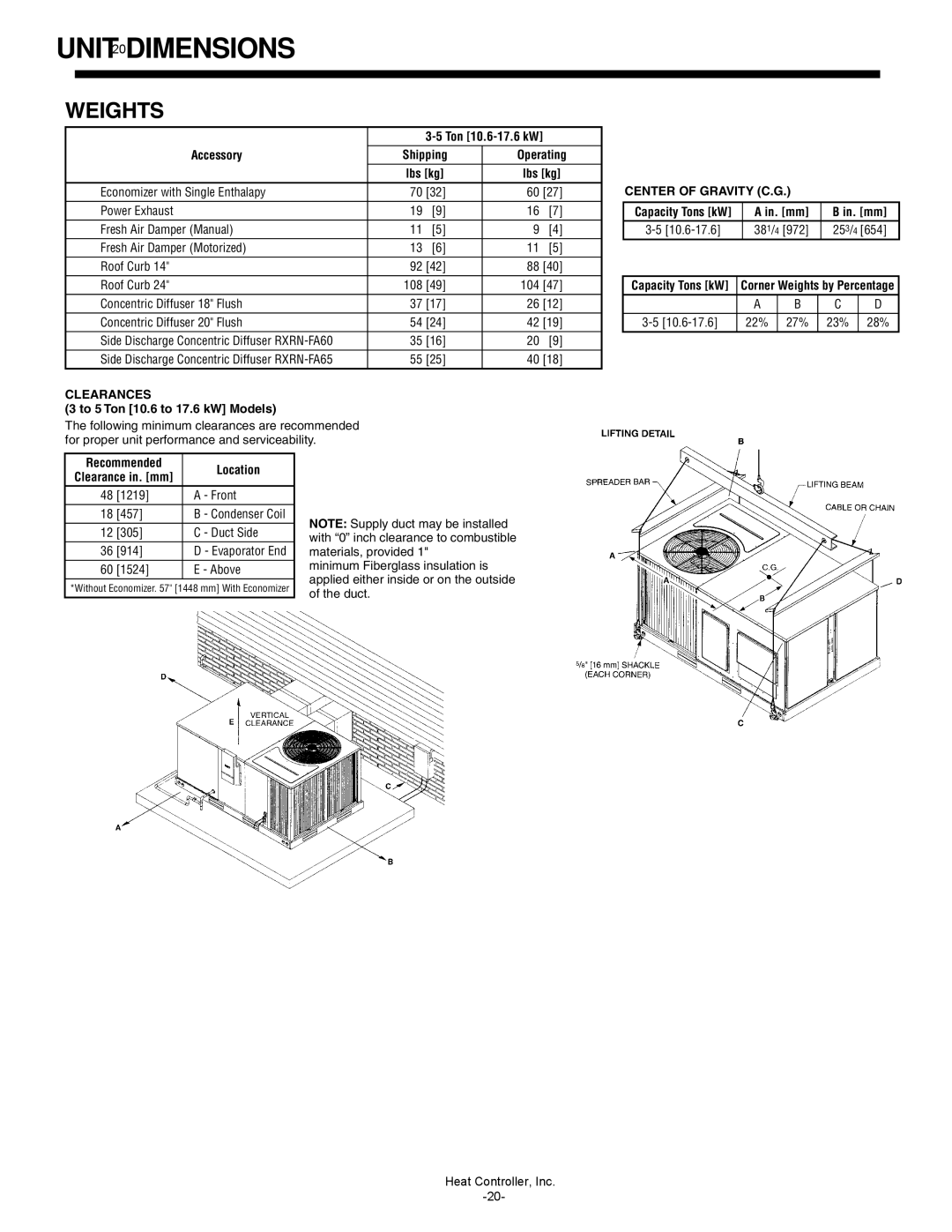
UNIT20DIMENSIONS, Weights
Models:
TGC048C-4K-135
TGC048C-1K-135
TGC060C-1K-135
TGC042C-3K-120
TGC060C-4K-135
TGC042C-4K-120
TGC042C-1K-120
TGC060C-3K-135
TGC048C-3K-135
1
20
35
35
Download
35 pages
11.14 Kb
17
18
19
20
21
22
23
24
Install
Dimension
Evaporator Coil/Filter Access
SELECTION6PROCEDURE EXAMPLE
RXRX-BFF04C-208/230V-1phase
Weight
ENGINEERING4FEATURES
Page 20
Image 20
Page 19
Page 21
Page 20
Image 20
Page 19
Page 21
Contents
TGC SERIES HIGH EFFICIENCY 13-SEER
NOMINAL SIZES 3-5TONS C VINTAGE
ENGINEERING DESIGN GUIDE
PACKAGE GAS ELECTRIC UNITS
TABLE2 OF CONTENTS
T G C
MODEL IDENTIFICATION
MODEL NOMENCLATURE - TGC SERIES
ENGINEERING4FEATURES
ENGINEERING FEATURES
INTRODUCTION
Evaporator Coil/Filter Access
Control Box Access
Compressor Access
SELECTION6PROCEDURE EXAMPLE
2.Select unit to meet cooling requirements
3.Select heating capacity of the unit
requirements
GENERAL7DATA
NOMINAL 3 TONS
GENERAL DATA
NOMINAL 3.5 TONS
GENERAL9DATA
NOMINAL 4 TONS
GENERAL10 DATA
NOMINAL 5 TONS
GROSS SYSTEM PERFORMANCE DATA-TGC042C
SYSTEM PERFORMANCE
GROSS SYSTEM PERFORMANCE DATA-TGC036C
SYSTEM PERFORMANCE
GROSS SYSTEM PERFORMANCE DATA-TGC048C
GROSS SYSTEM PERFORMANCE DATA-TGC060C
AIRFLOW PERFORMANCE DIRECT DRIVE
DIRECT-DRIVE208 VOLT AIRFLOW PERFORMANCE
14AIRFLOW PERFORMANCE-DIRECTDRIVE
DIRECT-DRIVE230 VOLT AIRFLOW PERFORMANCE
AIRFLOW PERFORMANCE-DIRECTDRIVE
DIRECT-DRIVE460 VOLT AIRFLOW PERFORMANCE
AIRFLOW PERFORMANCE-5TON BELT DRIVE
ELECTRICAL
ELECTRICAL DATA
ELECTRICAL DATA
Unit Information
UNIT DIMENSIONS
UNIT DIMENSIONS
PACKAGE GAS ELECTRIC UNITS
BOTTOM VIEW
Heat Controller, Inc
UNIT DIMENSIONS PACKAGE GAS ELECTRIC UNITS
UNIT DIMENSIONS
UNIT20DIMENSIONS
WEIGHTS
for Natural Gas Only ➀
ACCESSORIES
ACCESSORY EQUIPMENT-FIELDINSTALLED
ACCESSORIES22
ROOFCURBS Full Perimeter
TYPICAL INSTALLATION
ROOFCURB FOR TGC036C-TGC060CMODELS
ECONOMIZERS
ACCESSORIES
RXRD-KECM3-SingleEnthalpy with Barometric Relief
RXRX-AV02-DualEnthalpy Kit RXRX-AR02-CO2 Sensor
ACCESSORIES24
INTEGRAL POWER EXHAUST FOR ECONOMIZER
POWER EXHAUST KIT SPECIFICATIONS
FRESH AIR DAMPER
ACCESSORIES
DUCT ADAPTERS
Rectangular to Round Transitions Downflow
For use with Concentric Diffusers
ACCESSORIES26
DIMENSIONAL DATA
SIDE DISCHARGE CONCENTRIC DIFFUSER
ENGINEERING DATA
FLUSH MOUNT CONCENTRIC DIFFUSER
ACCESSORIES
DIMENSIONAL DATA
ENGINEERING DATA
ACCESSORIES28
THERMOSTATS GAS/ELECTRIC
RECOMMENDED THERMOSTATS WITH AND W/O ECONOMIZER
Single Stage Cool w/o Economizer
WIRING SCHEMATIC-TGC060C-1K w/X-13
Heat Controller, Inc
WIRING SCHEMATIC-TGC036/048C-1Kw/PSC
Heat Controller, Inc
WIRING SCHEMATIC-TGC036/060C-3Kw/PSC
Heat Controller, Inc
WIRING SCHEMATIC-TGC060C-3K w/X-13
Heat Controller, Inc
WIRING SCHEMATIC-TGC060C-4Kw/BELT DRIVE
Heat Controller, Inc
WIRING SCHEMATICS-TGC036/048C-4Kw/PSC
Heat Controller, Inc
Design, material, performance data and components
subject to change without notice
THE QUALITY LEADER IN CONDITIONING AIR
04/04/07
Top
Page
Image
Contents