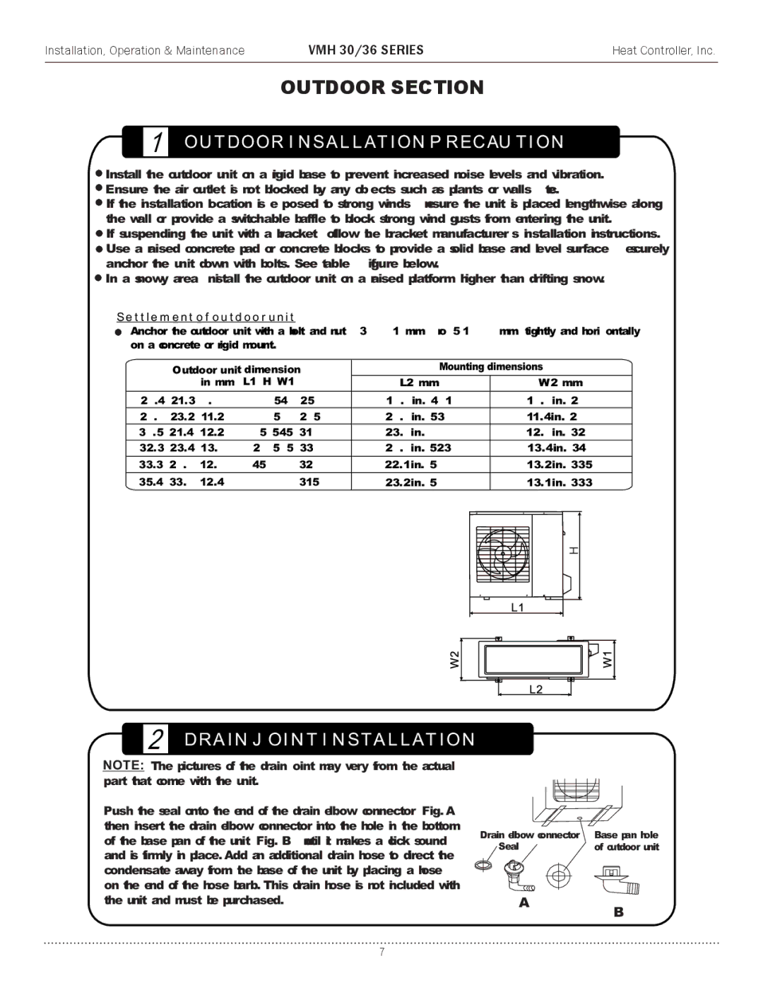
VMH 30 specifications
The Heat Controller VMH 30 is an advanced heating solution designed to provide efficient temperature control in various settings. This versatile unit is perfect for both residential and commercial spaces, making it a popular choice among homeowners and business owners alike. Known for its sleek design and high performance, the VMH 30 has garnered a positive reputation in the market.One of the standout features of the VMH 30 is its energy efficiency. It incorporates cutting-edge technologies that significantly reduce power consumption while maintaining optimal heating capabilities. The unit operates with a high Energy Efficiency Ratio (EER), ensuring that every kilowatt of electricity is utilized effectively. This not only contributes to lower energy bills but also promotes environmentally friendly usage.
The VMH 30 is equipped with advanced inverter technology, allowing it to adjust its heating output based on the room's temperature requirements. This dynamic capability results in a more accurate and stable climate control environment, enhancing comfort for its users. The inverter system also operates quietly, making it suitable for use in noise-sensitive areas, such as bedrooms and offices.
Another notable characteristic is its user-friendly interface. The VMH 30 comes with a digital thermostat that simplifies temperature management. Users can easily set their desired temperature and monitor the unit’s performance via an intuitive display. Many models also offer remote control capabilities through Wi-Fi connectivity, enabling users to adjust settings from their smartphones, even when they're not at home.
The VMH 30 is also designed with durability in mind. It features robust construction, ensuring that the unit withstands the test of time and performs consistently throughout its lifespan. The materials used in its build are resistant to corrosion and wear, providing added reliability.
In terms of installation, the VMH 30 offers flexibility, as it can be mounted on walls or ceilings, making it adaptable to different room layouts. Additionally, its compact size means it won’t occupy much space, allowing for optimal utilization of your room’s area.
Overall, the Heat Controller VMH 30 combines efficiency, performance, and user-friendly features to deliver a comprehensive heating solution. Its innovative technologies and thoughtful design makes it a preferred choice for those seeking reliable climate control. Whether used in a cozy home or a bustling office, the VMH 30 promises comfort and satisfaction throughout its entire operational life.

