Low pressure valve
Valve body Valve stem

Heat Controller, Inc.

VMH 30/36 SERIES

Installation, Operation & Maintenance


OUTDOOR SECTION

5AIR PURGING

1.Air purging

Air and moisture in the refrigerant system have undesirable effects. Therefore, the indoor unit and tubing between the indoor and outdoor unit must be leak tested and evacuated to remove any noncondensables and moisture from the system.

Check that each tube(both liquid and gas side tubes) between the indoor and outdoor units have been properly connected and all wiring for the test run has been completed.

Pipe length and refrigerant amount:

Units are pre-charged for 16.5 ft. (5m) total line set length, additional charge is needed for longer line sets lengths. Charge adjustments are not required for line sets less than 16.5 ft (5m)

Capacity

Pipe Size

Standard

Max

Total Line Length (ft)

Additional

Btu/h

Gas (in)

Liquid (in)

Length (ft)

Elevation (ft)

Min.

Max.

Refrigerant oz/ft

30-36k

5/8 (16mm)

3/8(9.52mm)

*16.5 (5m)

32 (9.75m)

10 (3m)

82 (25m)

.4 (40g/m)


*Unit charge located on rating plate includes enough refrigerant for 16.5 feet of line set.

*Charge adjustment is not required on line set lengths less than 16.5 feet. Ensure any R-410A refrigerant is added to the unit in liquid form.

CAUTION

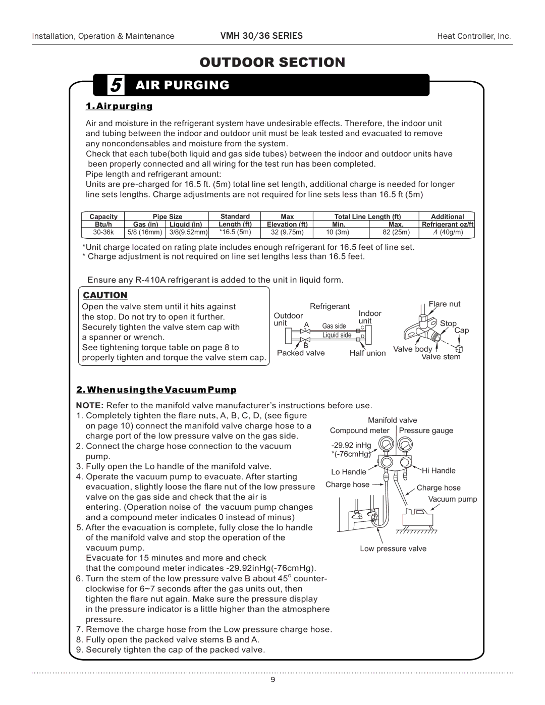
Open the valve stem until it hits against the stop. Do not try to open it further. Securely tighten the valve stem cap with a spanner or wrench.

See tightening torque table on page 8 to properly tighten and torque the valve stem cap.

Outdoor

Refrigerant


Indoor


unit

A Gas side


unit


C


Liquid side

D


B

Half union

Packed valve

Flare nut

Stop

Cap

2. When using the Vacuum Pump

NOTE: Refer to the manifold valve manufacturer’s instructions before use.


1.

Completely tighten the flare nuts, A, B, C, D, (see figure

Manifold valve


on page 10) connect the manifold valve charge hose to a


Compound meter

Pressure gauge


charge port of the low pressure valve on the gas side.


-29.92 inHg


2.

Connect the charge hose connection to the vacuum


pump.

*(-76cmHg)


3.

Fully open the Lo handle of the manifold valve.

Lo Handle

Hi Handle

4.

Operate the vacuum pump to evacuate. After starting

Charge hose


evacuation, slightly loose the flare nut of the low pressure

Charge hose


valve on the gas side and check that the air is


Vacuum pump


entering. (Operation noise of the vacuum pump changes


and a compound meter indicates 0 instead of minus)

5.After the evacuation is complete, fully close the lo handle of the manifold valve and stop the operation of the

vacuum pump.

Evacuate for 15 minutes and more and check

that the compound meter indicates -29.92inHg(-76cmHg).

6.Turn the stem of the low pressure valve B about 45O counter- clockwise for 6~7 seconds after the gas units out, then tighten the flare nut again. Make sure the pressure display in the pressure indicator is a little higher than the atmosphere pressure.

7.Remove the charge hose from the Low pressure charge hose.

8.Fully open the packed valve stems B and A.

9.Securely tighten the cap of the packed valve.

9

Page 9
Image 9
Heat Controller VMH 30 manual Air purging, When using the Vacuum Pump

VMH 30 specifications

The Heat Controller VMH 30 is an advanced heating solution designed to provide efficient temperature control in various settings. This versatile unit is perfect for both residential and commercial spaces, making it a popular choice among homeowners and business owners alike. Known for its sleek design and high performance, the VMH 30 has garnered a positive reputation in the market.

One of the standout features of the VMH 30 is its energy efficiency. It incorporates cutting-edge technologies that significantly reduce power consumption while maintaining optimal heating capabilities. The unit operates with a high Energy Efficiency Ratio (EER), ensuring that every kilowatt of electricity is utilized effectively. This not only contributes to lower energy bills but also promotes environmentally friendly usage.

The VMH 30 is equipped with advanced inverter technology, allowing it to adjust its heating output based on the room's temperature requirements. This dynamic capability results in a more accurate and stable climate control environment, enhancing comfort for its users. The inverter system also operates quietly, making it suitable for use in noise-sensitive areas, such as bedrooms and offices.

Another notable characteristic is its user-friendly interface. The VMH 30 comes with a digital thermostat that simplifies temperature management. Users can easily set their desired temperature and monitor the unit’s performance via an intuitive display. Many models also offer remote control capabilities through Wi-Fi connectivity, enabling users to adjust settings from their smartphones, even when they're not at home.

The VMH 30 is also designed with durability in mind. It features robust construction, ensuring that the unit withstands the test of time and performs consistently throughout its lifespan. The materials used in its build are resistant to corrosion and wear, providing added reliability.

In terms of installation, the VMH 30 offers flexibility, as it can be mounted on walls or ceilings, making it adaptable to different room layouts. Additionally, its compact size means it won’t occupy much space, allowing for optimal utilization of your room’s area.

Overall, the Heat Controller VMH 30 combines efficiency, performance, and user-friendly features to deliver a comprehensive heating solution. Its innovative technologies and thoughtful design makes it a preferred choice for those seeking reliable climate control. Whether used in a cozy home or a bustling office, the VMH 30 promises comfort and satisfaction throughout its entire operational life.