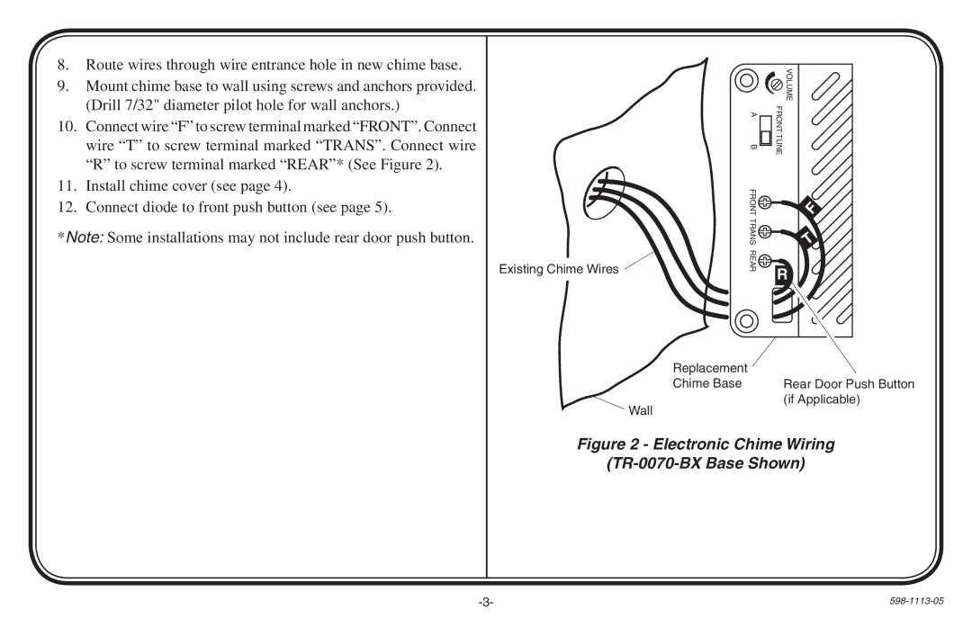
8.Route wires through wire entrance hole in new chime base.
9.Mount chime base to wall using screws and anchors provided. (Drill 7/32" diameter pilot hole for wall anchors.)
10.Connect wire “F” to screw terminal marked “FRONT”. Connect wire “T” to screw terminal marked “TRANS”. Connect wire “R” to screw terminal marked “REAR”* (See Figure 2).
11.Install chime cover (see page 4).
12.Connect diode to front push button (see page 5).
*Note: Some installations may not include rear door push button.
Existing Chime Wires ![]()
| VOLUME | |
A | FRONT | |
B | TUNE | |
FRONT | F | |
TRANS | ||
T | ||
REAR | R | |
|
Replacement ![]()
Chime Base Rear Door Push Button
Wall
(if Applicable)
Figure 2 - Electronic Chime Wiring
(TR-0070-BX Base Shown)
- - |
