BUILDER'S CHOICE SERIES INSTALLATION INSTRUCTIONS
2.VERTICAL TERMINATION
a.Clearances
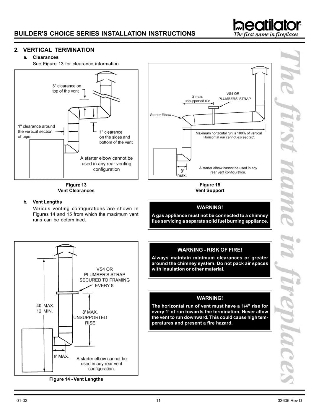
See Figure 13 for clearance information.
Figure 13
Vent Clearances
b.Vent Lengths
Various venting configurations are shown in Figures 14 and 15 from which the maximum vent runs can be determined.
Figure 15
Vent Support
WARNING!
A gas appliance must not be connected to a chimney flue servicing a separate solid fuel burning appliance.
WARNING - RISK OF FIRE!
Always maintain minimum clearances or greater around the chimney system. Do not pack air spaces with insulation or other material.
WARNING!
The horizontal run of vent must have a 1/4” rise for every 1’ of run towards the termination. Never allow the vent to run downward. This could cause high tem- peratures and present a fire hazard.
Figure 14 - Vent Lengths
11 | 33606 Rev D |
