BUILDER'S CHOICE SERIES INSTALLATION INSTRUCTIONS
4. WIRING
Standing Pilot Ignition - Millivolt System
a.Appliance Requirements
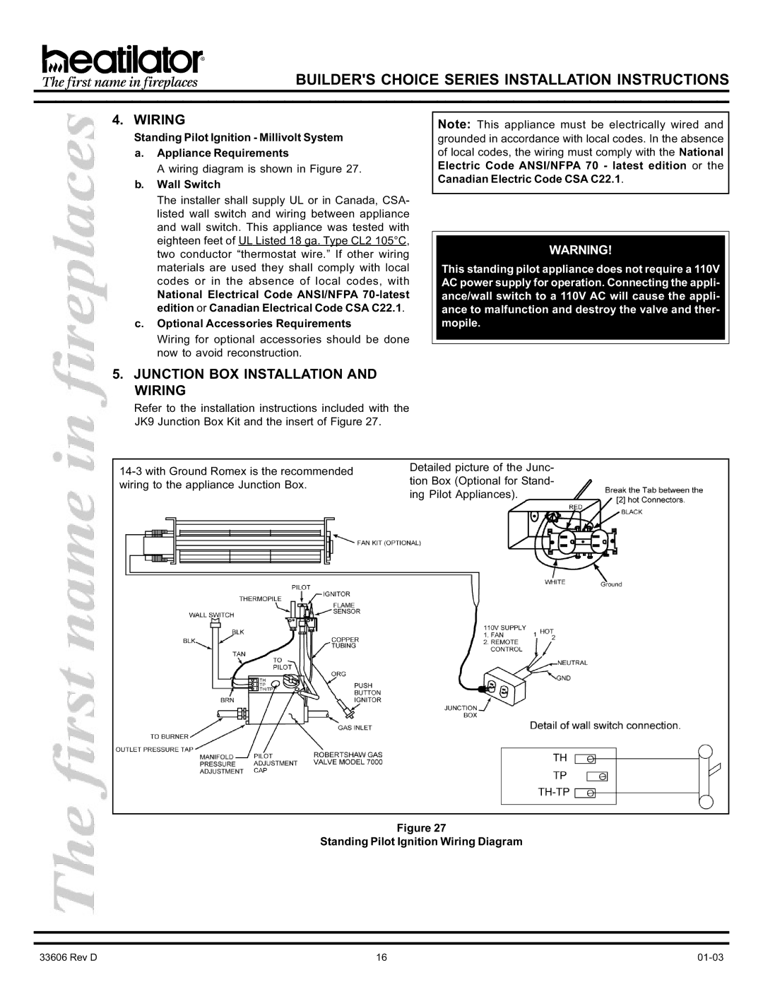
A wiring diagram is shown in Figure 27.
b.Wall Switch
The installer shall supply UL or in Canada, CSA- listed wall switch and wiring between appliance and wall switch. This appliance was tested with eighteen feet of UL Listed 18 ga. Type CL2 105°C, two conductor “thermostat wire.” If other wiring materials are used they shall comply with local codes or in the absence of local codes, with
National Electrical Code ANSI/NFPA
c.Optional Accessories Requirements
Wiring for optional accessories should be done now to avoid reconstruction.
5.JUNCTION BOX INSTALLATION AND WIRING
Note: This appliance must be electrically wired and grounded in accordance with local codes. In the absence of local codes, the wiring must comply with the National Electric Code ANSI/NFPA 70 - latest edition or the Canadian Electric Code CSA C22.1.
WARNING!
This standing pilot appliance does not require a 110V AC power supply for operation. Connecting the appli- ance/wall switch to a 110V AC will cause the appli- ance to malfunction and destroy the valve and ther- mopile.
Refer to the installation instructions included with the JK9 Junction Box Kit and the insert of Figure 27.
Detailed picture of the Junc- tion Box (Optional for Stand- ing Pilot Appliances).
Figure 27
Standing Pilot Ignition Wiring Diagram
33606 Rev D | 16 |