NOTE: These components are affixed with glue. Be careful not to break or damage any foil under the component or at the pins of the ICs when removing. Usually applying heat to the component for a short time while twisting with tweezers will break the component loose.

Leadless Chip Components (surface mount)

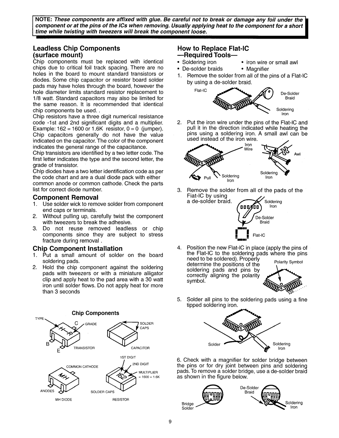
Chip components must be replaced with identical chips due to critical foil track spacing. There are no holes in the board to mount standard transistors or diodes. Some chip capacitor or resistor board solder pads may have holes through the board, however the hole diameter limits standard resistor replacement to l/8 watt. Standard capacitors may also be limited for the same reason. It is recommended that identical chip components be used. .

Chip resistors have a three digit numerical resistance code -1st and 2nd significant digits and a multiplier. Example: 162 = 1600 or 1.6K resistor, 0 = 0 (jumper). Chip capacitors generally do not have the value indicated on the capacitor. The color of the component indicates the general range of the capacitance.

Chip transistors are identified by a two letter code. The first letter indicates the type and the second letter, the grade of transistor.

Chip diodes have a two letter identification code as per the code chart and are a dual diode pack with either common anode or common cathode. Check the parts list for correct diode number.

Component Removal

1.Use solder wick to remove solder from component end caps or terminals.

2.Without pulling up, carefully twist the component with tweezers to break the adhesive.

3.Do not reuse removed leadless or chip components since they are subject to stress fracture during removal .

Chip Component Installation

1.Put a small amount of solder on the board soldering pads.

2.Hold the chip component against the soldering pads with tweezers or with a miniature alligator clip and apply heat to the pad area with a 30 watt iron until solder flows. Do not apply heat for more than 3 seconds

Chip Components

TypE13$F:;:;63:

1ST DIGIT

MH DIODE

RESISTOR

How to Replace Flat-IC -Required Tools-

*

Soldering

iron

l

iron wire

or small awl

l

De-solder

braids

l

Magnifier


1.Remove the solder from all of the pins of a Flat-IC by using a de-solder braid.

Flat-IC

De-Solder

Braid

Soldering

Iron

2.Put the iron wire under the pins of the Flat-IC and pull it in the direction indicated while heating the pins using a soldering iron. A small awl can be

used instead of the iron wire.

/

Iron

Wire

Awl

3.Remove the solder from all of the pads of the Fiat-IC by using

a de-solder braid.

~-“‘! Flat-IC --WI-

4.Position the new Flat-IC in place (apply the pins of the Flat-IC to the soldering pads where the pins

need to be soldered). Properly

Polarity Symbol

determine the positions of the


soldering pads and pins by


correctly aligning the polarity


symbol.


5.Solder all pins to the soldering pads using a fine tipped soldering iron.

6.Check with a magnifier for solder bridge between the pins or for dry joint between pins and soldering pads. To remove a solder bridge, use a de-solder braid as shown in the figure below.


D

Bridge

oldering

Iron

Solder


Page 9
Image 9
Hitachi 60SBX78B, 50SBX78B service manual Soldering Iron Iron wire, Determine the positions

60SBX78B, 50SBX78B specifications

The Hitachi 50SBX78B and 60SBX78B are advanced plasma televisions that represent the pinnacle of display technology in their respective categories. These models bring together innovative features, cutting-edge technology, and sleek design, ensuring an immersive viewing experience for consumers.

One of the standout characteristics of the Hitachi 50SBX78B and 60SBX78B is their screen size, with the 50-inch model catering to smaller spaces while the 60-inch offers a more cinematic experience. Both models boast impressive Full HD resolution, delivering a crisp and vibrant picture quality that enhances any viewing experience, whether it be movies, sports, or gaming.

The technology behind these televisions includes Hitachi's proprietary image processing technology, which optimizes picture quality by minimizing noise and enhancing color accuracy. This leads to deeper blacks and brighter whites, ensuring that every scene is rendered with stunning detail. The Plasmavision technology further enhances the black levels and contrast ratios, making images pop off the screen.

In addition to superior image quality, both models come equipped with a variety of connectivity options. Multiple HDMI inputs allow users to easily connect various devices such as gaming consoles, Blu-ray players, and streaming devices. The inclusion of USB ports facilitates easy viewing of photos and videos stored on external drives.

Moreover, Hitachi televisions have integrated audio technologies that enhance the overall viewing experience. The built-in speakers provide clear sound, while the digital audio output allows for connection to external sound systems, giving consumers the flexibility to customize their audio experience.

Energy efficiency is also a notable feature of the Hitachi 50SBX78B and 60SBX78B models. They are designed to consume less power than traditional televisions, aligning with the growing demand for environmentally friendly electronics. This not only reduces electricity bills but also minimizes the carbon footprint.

The sleek and modern design of these plasma televisions makes them an attractive addition to any home décor. The slim bezel offers a larger screen-to-body ratio, maximizing the viewing area while maintaining an elegant appearance.

In summary, the Hitachi 50SBX78B and 60SBX78B offer a compelling package of features, technologies, and characteristics that cater to the needs of modern viewers. With superior image quality, versatile connectivity, and energy efficiency, these televisions are designed to deliver an exceptional home entertainment experience.