CR 13VA specifications
The Hitachi CR 13VA is a powerful and versatile reciprocating saw designed for both professional contractors and DIY enthusiasts. Known for its robust performance and innovative features, this tool stands out in the market for its efficiency and ease of use.One of the main features of the CR 13VA is its impressive motor. With a peak power input of 1,200 watts, this saw provides strong cutting performance, enabling users to deal with a wide range of materials including wood, metal, and plastic. The tool also boasts a variable speed control, allowing users to adjust the cutting speed between 0 to 2,800 strokes per minute. This feature is crucial for achieving optimal performance when tackling different materials or tasks, ensuring a clean and precise cut every time.
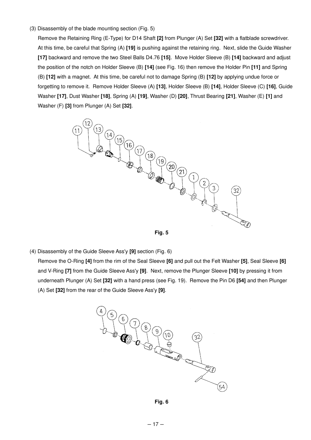
The CR 13VA is designed with user comfort in mind. Its ergonomic handle reduces vibrations and fatigue, making extended use more manageable. Additionally, the saw features a lightweight construction that enhances maneuverability, allowing users to work in tight spaces without compromising control. The blade change system is another highlight, featuring a quick-release mechanism that allows for fast and tool-free blade changes, ensuring that users can swap blades efficiently without wasting time.
Another noteworthy technology in the CR 13VA is its electronic speed control system. This system maintains a consistent cutting speed under load, which is essential for maintaining cutting efficiency, especially in tougher materials. Coupled with its adjustable base and pivoting shoe, users can make cleaner cuts at different angles and depths, enhancing the versatility of the tool for various projects.
Safety is also a top priority with the Hitachi CR 13VA. The saw includes a safety lock switch that prevents accidental operation, and the protective guard helps to reduce debris projection while cutting. This combination of features not only protects the user but also prolongs the life of the tool.
In summary, the Hitachi CR 13VA is an ideal choice for those seeking a reliable and effective reciprocating saw. With its powerful motor, variable speed control, ergonomic design, quick blade change system, and safety features, it delivers exceptional performance across a diverse range of applications, making it a valuable asset for any toolkit. Whether for professional use or home improvement projects, the CR 13VA exemplifies quality and functionality.

