5. Dipstick insertion and oil level check

Use a screwdriver or similar tool to remove the plastic cap on the lower part of the cylinder (Fig. 3).

Cylinder

Plastic cap

Fig. 3

Insert the accessory dipstick all the way to the bottom. Remove the dipstick and make sure the oil level is within the range of the dipstick notches (Fig. 4).

Dipstick

Air vent

MAX.

MIN.

Fig. 4

WARNING: Drain tank to release air pressure before removing the dipstick.

WARNING: Make sure air vent in dipstick is free from debris. If air vent is blocked pressure can build in crankcase causing damage to compressor and possible personal injury.

When the oil volume is insufficient, refer to the section ÒOil change-oil topping offÓ on page 13 for a description of how to supply the oil.

6. Air coupler installation

Screw in the air coupler to the joint (Refer to Fig. 1 and Fig. 7). The screw size of the joint is 3/8". Use an air coupler which has the same screw size.

7. Right running position

Position the compressor on a flat surface or one with an inclination of 10¡ at the most, in a well ventilated area away from atmospheric agents and not in explosive areas.

CAUTION: In order to avoid damaging the compressor, do not allow the unit to be tilted more than 10° when operating.

English

8. Correct placement of the compressor

NOTE: When operating or storing the compressor, set 4 rubber bumpers downward on the floor. (Refer to Fig. 1)

9. Temperature

Operating temperatures are between 32¡F and 104¡F (0¡C and 40¡C).

CAUTION: Never operate in temperatures below 32°F (0°C) or above 104°F (40°C).

TRANSPORT

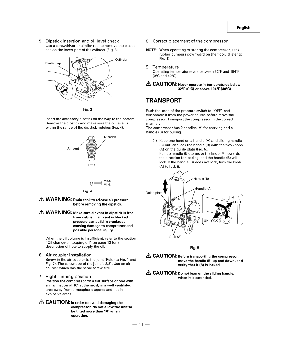
Push the knob of the pressure switch to ÒOFFÓ and disconnect it from the power source before move the compressor. Transport the compressor in the correct manner.

The compressor has 2 handles (A) for carrying and a handle (B) for pulling.

(1)Keep one hand on a handle (A) and sliding handle

(B)out, and lock the handle (B) with the two knobs

(A)on the guide plate (Fig. 5).

Pull up handle (B), to move the knob (A) towards the direction for locking, and the handle (B) will lock. If the handle (B) does not lock, turn the knob

(A)to lock it.

Handle (B)

Handle (A)

Guide plate

LOCK

UN LOCK

Knob (A)

Fig. 5

CAUTION: Before transporting the compressor, move the handle (B) up and down, and verify that it (B) is locked.

CAUTION: Do not lean on the sliding handle, when it is extended.

Ñ 11 Ñ

Page 11
Image 11
Hitachi EC 129 instruction manual Transport, 11 Ñ

EC 129 specifications

The Hitachi EC 129 is a cutting-edge electric compressor designed to meet the demanding requirements of various industrial applications. With its robust construction and advanced engineering, the EC 129 stands out for its efficiency and reliability, making it a preferred choice for businesses looking to enhance their productivity.

One of the main features of the Hitachi EC 129 is its powerful motor, which operates efficiently while delivering a high airflow rate. This feature ensures that the compressor can easily handle a range of tasks, from powering pneumatic tools to supporting larger systems. The EC 129's motor is specifically engineered for reduced power consumption without sacrificing performance, which translates to lower operational costs for businesses.

In terms of technology, the Hitachi EC 129 incorporates a sophisticated variable frequency drive (VFD). This innovative feature allows the compressor to adjust its speed according to demand, resulting in improved energy efficiency. The VFD not only enhances performance but also prolongs the lifespan of the machine by reducing wear and tear on its components.

Another significant characteristic of the EC 129 is its compact design. Unlike traditional compressors that require substantial floor space, the EC 129 is engineered to fit into confined spaces without compromising on performance. This makes it an ideal solution for industrial environments where space is at a premium.

The EC 129 also boasts advanced noise reduction technologies, making it one of the quieter models in its class. This is particularly advantageous in workplaces where noise levels must be kept to a minimum for safety and comfort. The compressor operates smoothly, ensuring that it does not disrupt the working environment while delivering consistent performance.

Maintenance is made easy with the Hitachi EC 129, featuring user-friendly access to critical components for routine checks and servicing. This ensures that the compressor can be kept in optimal condition, guaranteeing uninterrupted service and reliability.

Overall, the Hitachi EC 129 combines power, advanced technology, and user-friendly features, making it a top choice for industries that demand efficient and reliable compressed air solutions. Whether in manufacturing, construction, or other sectors, the EC 129 promises to deliver exceptional performance tailored to diverse operational needs.