(Continued from previous page)
Display | Function | Standard | Set |
Setting | Value | ||
A 0 | Characteristic V/F curve setting | 0 |
|
|
|
| |
|
|
| |
|
|
| |
A 1 | Motor capacity setting | Cf. nameplate |
|
A 2 | Motor poles: 2, 4, 6, 8 | 4 |
|
A 3 | ASR constant | 2 |
|
A 4 | Start frequency setting | 0.5 |
|
A 5 | Maximum operating frequency setting | 0 |
|
A 6 | Minimum operating frequency setting | 0 |
|
A 7 | Jump frequency setting | 0 |
|
A 8 |
|
|
|
A 9 |
|
|
|
A10 | Carrier frequency (in kHz) | Depends on |
|
|
| model |
|
Display |
|
| Function | Standard | Set |
|
| Setting | Value | ||
|
|
|
| ||
A94 | PID feedback signal location / I gain setting | 0 |
| ||
|
|
| |||
|
|
| |||
|
|
| |||
A95 | PID control set value setting | 0 |
| ||
|
|
| |||
A96 | PID control internal set value (in %) | 0 |
| ||
A97 | Autotuning mode: | 0 |
| ||
|
|
| |||
A98 | Motor data: | 0- Standard Hitachi | 0 |
| |
| special motors |
|
| ||
A99 | Power supply phase breakdown will cause | 0 |
| ||
| trip E24: |
|
| ||
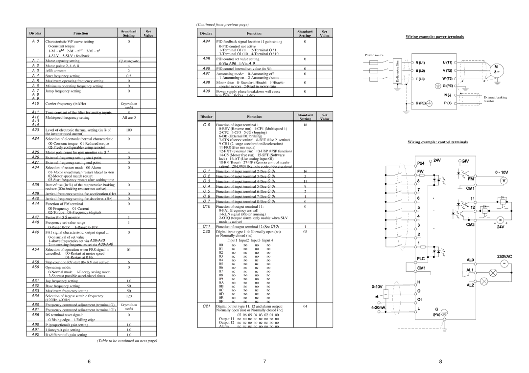
Power source
Wiring example: power terminals
Radio noise filter
External braking resistor
A11 | Time constant of the filter for analog inputs | 8 |
|
| |||
A12 | Multispeed frequency setting | All are 0 |
|
| |||
A13 |
|
|
|
|
|
|
|
A14 |
|
|
|
|
|
|
|
A23 | Level of electronic thermal setting (in % of | 100 |
|
| |||
| the inverter rated current) |
|
|
| |||
A24 | Selection of electronic thermal characteristic | 0 |
|
| |||
|
|
|
| ||||
|
|
|
| ||||
A25 | Motor pole count for rpm monitor via d 1 | 4 |
|
| |||
A26 | External frequency setting start point | 0 |
|
| |||
A27 | External frequency setting end point | 0 |
|
| |||
A34 | Selection of restart mode | 0 |
|
| |||
|
|
|
| ||||
|
|
|
| ||||
|
|
|
| ||||
A38 | Rate of use (in %) of the regenerative braking | 0 |
|
| |||
| resistor (00= braking resistor not active) |
|
|
| |||
A39 | Arrival frequency setting for acceleration (Hz) | 0 |
|
| |||
A40 | Arrival frequency setting for decelerat. (Hz) | 0 |
|
| |||
A44 | Function of FM terminal | 0 |
|
| |||
|
|
|
| ||||
|
|
|
| ||||
A47 | Factor for d 3 monitor | 1 |
|
| |||
A48 | Frequency set value range | 1 |
|
| |||
|
|
|
| ||||
A49 | FA1 signal characteristic: output signal ... | 0 |
|
| |||
|
|
|
| ||||
|
|
|
| ||||
|
|
|
| ||||
A54 | Selection of operation when FRS signal is | 01 |
|
| |||
| cancelled: |
|
|
| |||
|
|
|
|
| |||
A58 | Step count on RV start (0= RV not active) | 6 |
|
| |||
A59 | Operating mode: |
|
| 0 |
|
| |
|
|
|
| ||||
|
|
|
| ||||
A61 | Jog frequency setting | 1.0 |
|
| |||
A62 | Base frequency setting | 50 |
|
| |||
A63 | Maximum frequency setting | 50 |
|
| |||
A64 | Selection of largest settable frequency | 120 |
|
| |||
| (120Hz, 400Hz) |
|
|
|
|
| |
A80 | Frequency command adjustment (terminal O) | Depends on |
|
| |||
A81 | Frequency command adjustment (terminal OI) | model |
|
| |||
A86 | RS terminal reset signal: | 0 |
|
| |||
|
|
|
| ||||
A90 | P (proportional) gain setting | 1.0 |
|
| |||
A91 | I (integral) gain setting | 1.0 |
|
| |||
A92 | D (differential) gain setting | 1.0 |
|
| |||
Display | Function | Standard | Set | |
Setting | Value | |||
|
|
C 0 | Function of input terminal 1 |
| 18 |
| |||
|
|
| |||||
|
|
| |||||
|
|
|
| ||||
|
|
| |||||
|
|
| |||||
|
|
|
| ||||
|
|
| |||||
|
|
| |||||
| lock) |
|
| ||||
|
|
| |||||
| ration) |
|
| ||||
C 1 | Function of input terminal 2 (See C 0) | 16 |
| ||||
C 2 | Function of input terminal 3 (See C 0) | 5 |
| ||||
C 3 | Function of input terminal 4 (See C 0) | 11 |
| ||||
C 4 | Function of input terminal 5 (See C 0) | 9 |
| ||||
C 5 | Function of input terminal 6 (See C 0) | 2 |
| ||||
C 6 | Function of input terminal 7 (See C 0) | 1 |
| ||||
C 7 | Function of input terminal 8 (See C 0) | 0 |
| ||||
C10 | Function of output terminal 11: |
| 0 |
| |||
|
|
|
| ||||
|
|
|
| ||||
|
|
| |||||
| mode is active) |
|
|
|
|
| |
C11 | Function of output terminal 12 (See C10) | 1 |
| ||||
C20 | Digital input type | 08 |
| ||||
| or Normally closed (nc) |
|
|
|
| ||
| Input1 Input2 Input3 Input 4 |
|
| ||||
| 00 | no | no | no | no |
|
|
| 01 | nc | no | no | no |
|
|
| 02 | no | nc | no | no |
|
|
| 03 | nc | nc | no | no |
|
|
| 04 | no | no | nc | no |
|
|
| 05 | nc | no | nc | no |
|
|
| 06 | no | nc | nc | no |
|
|
| 07 | nc | nc | nc | no |
|
|
| 08 | no | no | no | nc |
|
|
| 09 | nc | no | no | nc |
|
|
| 0A | no | nc | no | nc |
|
|
| 0B | nc | nc | no | nc |
|
|
| 0C | no | no | nc | nc |
|
|
| 0D | nc | no | nc | nc |
|
|
| 0E | no | nc | nc | nc |
|
|
| 0F | nc | nc | nc | nc |
|
|
C21 | Digital output type 11, 12 and alarm output: | 04 |
| ||||
| Normally open (no) or Normally closed (nc) |
|
| ||||
|
| 07 06 05 04 03 02 01 00 |
|
| |||
| Output 11 nc no nc no nc no nc no |
|
| ||||
| Output 12 nc nc no no nc nc no no |
|
| ||||
| Alarm | nc nc nc nc no no no no |
|
| |||
Wiring example: control terminals
(Table to be continued on next page)
6 | 7 |