HITACHI INVERTER
J300 SERIES
QUICK REFERENCE GUIDE (Part 2/2)
Three phase input 400V
CE-EMC Installation
This instruction describes the electromagnetically compatible setup of your drive system.
1.As an enduser you must ensure that the HF impedance between frequency inverter, filter and ground is as small as possible.
∙See to it that the connections are metallic and have the largest possible areas
2.Conductor loops act like antennas, especially when they encompass large areas. Consequently:
∙Avoid unnecessary conductor loops
∙Avoid parallel arrangement of „clean“ and
3.Lay the motor cable and all analog and digital contol lines shielded.
∙You should allow the effective shield area of these lines to remain as large as possible; i.e., do not move the shield further away than absolutely necessary.
∙With compact systems, if for example the frequency inverter is communicating with the steering unit, in the same control cabinet connected at the same
∙The large area contact between shield and
∙Use only copper mesh cable (CY) with 85% coverage
∙The shielding should not be interrupted at any point in the cable. If the use of reactors, contactors, terminals or safety switches in the motor output is necessary, the unshielded section should be kept as small as possible.
∙Some motors have a rubber gasket between terminal box and motor housing. Very often, the terminal boxes, and particularly the threads for the metal PG screw connections, are painted. Make sure there is always a good metallic connection between the shielding of the motor cable, the metal PG screw connection, the terminal box and the motor housing, and carefully remove this paint if necessary.
4.Very frequently, interference is coupled in through installation cables. This influence you can minimize:
∙Lay interfering cables separately, a minimum of 0.25 m from cables susceptible to interference.A particularly critical point is laying cables parallel over larger distances. If two cables intersect, the interference is
smallest if they intersect at an angle of 90°. Cables susceptible to interference should therefore only intersect motor cables, intermediate circuit cables, or the wiring of a rheostat at right angles and never be laid parallel to them over larger distances.
5.The distance between an interference source and an interference sink
∙You should use only
6.Safety measures
∙Ensure that the protective conductor terminal (PE) of the filter is properly connected with the protective conductor terminal of the frequency inverter. An HF ground connection via metal contact between the housings of the filter and the frequency inverter, or solely via cable shield, is not permitted as protective conductor connection. The filter must be solidly and permanently connected with the ground potential so as to preclude the danger of electric shock upon touching the filter if a fault occurs. You can achieve this by:
-connecting it with a grounding conductor of at least 10 mm2;
-connecting a second grounding conductor, connected with a separate grounding terminal, parallel to the protective conductor (The cross section of each single protective conductor terminal
| must be designed for the required6KLHOGHGFDEOHVnominalFRQWUROload) | 6KLHOGHGFDEOHVPRWRU | ||||
|
|
|
|
|
|
|
|
|
|
|
|
|
|
|
|
|
|
|
|
|
|
|
|
|
|
|
|
|
|
|
|
|
|
|
|
|
|
|
|
|
|
|
|
|
|
|
|
|
|
|
|
|
|
|
|
|
|
|
|
|
|
|
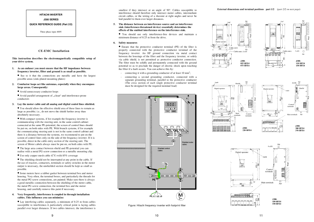
Figure: Hitachi frequency inverter with footprint filter
|
| External dimensions and terminal positions part 1/2 | (part 2/2 on next page) | ||||||||||||||||||||||||
|
|
|
|
|
|
|
|
|
|
|
|
|
|
|
|
|
|
|
|
|
|
|
|
|
|
|
|
|
|
|
|
|
|
|
|
| Air |
|
|
|
|
|
|
|
|
|
|
|
|
| Air |
|
| ||
|
|
|
|
|
|
|
|
|
|
|
|
|
|
|
|
|
|
|
|
|
|
|
|
|
|
| |
|
|
|
|
|
|
|
|
|
|
| Wall |
|
|
|
|
|
|
|
|
|
|
|
|
|
|
|
|
|
|
|
|
|
|
|
|
|
|
|
|
|
|
|
| Wall |
| ||||||||||
|
|
|
|
|
|
|
|
|
|
|
|
|
|
|
|
|
|
|
|
|
|
|
|
|
|
| |
|
|
|
|
|
|
|
|
|
|
|
|
|
|
|
|
|
|
|
|
|
|
|
|
|
|
|
|
|
| Digital operator |
|
|
|
|
|
|
|
|
|
|
|
|
|
|
|
|
|
|
|
|
|
|
|
| |
|
|
|
|
|
|
|
|
|
|
|
|
|
|
|
|
|
|
|
|
|
|
|
|
|
|
|
|
|
|
|
|
| Cable entry |
|
|
|
|
|
|
|
|
|
|
|
|
|
|
|
|
|
|
|
| ||
|
|
|
|
|
| Air |
|
|
|
|
|
|
|
|
|
|
|
|
|
|
|
|
| ||||
|
|
|
|
|
|
| Cable entry |
|
|
|
|
|
|
|
|
|
| Cable entry |
|
|
|
|
|
| |||
|
|
|
|
|
|
|
|
|
|
|
|
|
|
|
|
|
|
|
|
|
|
|
| Air |
|
| |
|
|
|
|
|
|
|
| J300- |
|
|
|
| J300- | ||||||||||||||
|
|
|
|
|
|
|
| 055 HFE4 |
|
|
|
| 110 HFE4 | ||||||||||||||
|
|
|
|
|
|
|
| 075 HFE4 |
|
|
|
| 150 HFE4 | ||||||||||||||
|
|
|
|
|
|
|
|
|
|
|
|
|
|
|
|
|
|
|
|
|
|
|
|
|
|
|
|
|
|
|
|
|
|
|
|
|
|
|
|
|
|
|
|
|
|
|
|
|
|
|
|
|
|
| |
|
|
|
|
|
|
|
|
| Air |
|
|
|
|
|
|
|
|
|
|
| Air |
|
| ||||
|
|
|
|
|
|
| Handle |
|
|
|
|
|
|
|
|
|
|
|
|
|
|
| |||||
|
|
|
|
|
|
|
|
|
|
|
|
|
|
|
|
|
|
|
|
|
|
|
|
|
|
| |
|
|
|
|
|
|
|
|
|
|
|
|
|
|
|
|
|
|
|
|
|
|
|
|
|
|
|
|
| Digital operator |
|
|
|
|
|
|
|
|
|
|
|
| Digital operator |
|
|
|
|
| Handle |
|
| |||||
|
|
|
|
|
|
|
|
|
|
|
|
|
|
|
|
|
|
|
|
|
|
|
|
|
|
|
|
|
|
|
|
|
|
|
|
|
|
|
|
|
|
|
|
|
|
|
|
|
|
|
|
|
| Wall |
|
|
|
|
|
|
|
|
|
|
|
|
|
| Wall |
|
|
|
|
|
|
|
|
|
|
|
|
| |
|
|
|
|
|
|
|
|
|
|
|
|
|
|
|
|
|
|
|
|
|
|
|
|
|
|
| |
|
|
|
|
|
|
|
|
|
|
|
|
|
|
|
|
|
|
|
| Control |
|
|
|
|
|
| |
|
|
|
|
|
|
|
|
|
|
|
|
|
|
|
|
|
|
|
| terminals |
|
|
|
|
|
| |
|
|
|
|
|
|
|
|
|
|
|
|
|
|
|
|
|
|
|
|
|
|
|
|
|
|
|
|
|
|
|
|
|
|
|
|
|
|
|
|
|
|
|
|
|
|
|
|
|
|
|
|
|
|
|
|
|
|
|
|
|
|
| Main |
| Control |
|
|
|
|
|
|
| Main terminals |
| Air |
|
| ||||||
|
|
|
|
|
|
| terminals |
|
|
|
|
|
|
|
|
|
|
| |||||||||
|
|
|
|
|
|
|
| terminals |
|
|
|
|
|
|
|
|
|
|
|
|
|
|
| ||||
|
|
|
|
|
|
|
|
| J300- |
|
|
|
| J300- |
| ||||||||||||
|
|
|
|
|
|
|
|
|
|
|
|
| 300 HFE4 |
| |||||||||||||
|
|
|
|
|
|
|
|
| 220 HFE4 |
|
|
|
| 370 HFE4 |
| ||||||||||||
|
|
|
|
|
|
|
|
|
|
|
|
|
|
|
|
|
|
|
|
|
| ||||||
|
|
|
|
|
|
|
|
|
|
|
|
|
|
|
|
|
| Air | |||||||||
|
|
|
|
|
|
|
|
|
|
|
|
|
|
|
|
|
| ||||||||||
|
|
|
|
|
|
| Digital operator |
|
|
|
|
|
|
|
|
|
|
| |||||||||
|
|
|
|
|
|
|
|
|
|
|
|
|
|
|
|
|
|
|
|
|
|
|
|
|
|
|
|
|
|
|
|
|
|
|
|
|
|
|
|
|
|
|
|
|
|
|
| Wall |
| ||||||
|
|
|
|
|
|
|
|
|
|
|
|
|
|
|
|
|
|
|
|
|
|
|
|
|
|
|
|
|
|
|
|
|
|
|
|
|
|
|
|
|
|
|
|
|
|
|
|
|
|
|
|
|
|
|
|
|
|
|
|
|
|
|
|
|
|
|
|
|
|
|
| Control |
|
|
|
|
|
|
|
|
|
| |
|
|
|
|
|
|
|
|
|
|
|
|
|
|
|
| terminals |
|
|
|
|
|
|
|
|
|
|
|
Main terminals | Air |
|
J300-
450 HFE4
550 HFE4
9 | 10 | 11 |