S-0007-E

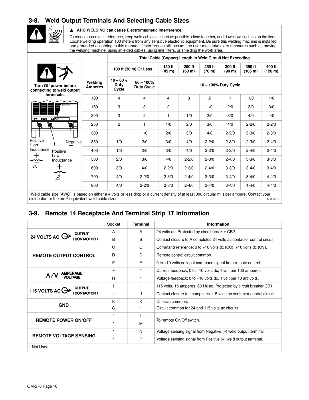
3-8. Weld Output Terminals And Selecting Cable Sizes

Y ARC WELDING can cause Electromagnetic Interference.

To reduce possible interference, keep weld cables as short as possible, close together, and down low, such as on the floor. Locate welding operation 100 meters from any sensitive electronic equipment. Be sure this welding machine is installed and grounded according to this manual. If interference still occurs, the user must take extra measures such as moving the welding machine, using shielded cables, using line filters, or shielding the work area.


Total Cable (Copper) Length In Weld Circuit Not Exceeding


100 ft (30 m) Or Less

150 ft

200 ft

250 ft

300 ft

350 ft

400 ft


(45 m)

(60 m)

(70 m)

(90 m)

(105 m)

(120 m)


Welding

10 – 60%

60 – 100%


Turn Off power before

Duty


10 – 100% Duty Cycle


Amperes

Duty Cycle


connecting to weld output

Cycle


terminals.

100

4

4

4

3

2

1

1/0

1/0


150

3

3

2

1

1/0

2/0

3/0

3/0


200

3

2

1

1/0

2/0

3/0

4/0

4/0


250

2

1

1/0

2/0

3/0

4/0

2-2/0

2-2/0


300

1

1/0

2/0

3/0

4/0

2-2/0

2-3/0

2-3/0

Positive

Negative

350

1/0

2/0

3/0

4/0

2-2/0

2-3/0

2-3/0

2-4/0

High


Inductance Positive

400

1/0

2/0

3/0

4/0

2-2/0

2-3/0

2-4/0

2-4/0


Low

500

2/0

3/0

4/0

2-2/0

2-3/0

2-4/0

3-3/0

3-3/0


Inductance


600

3/0

4/0

2-2/0

2-3/0

2-4/0

3-3/0

3-4/0

3-4/0


700

4/0

2-2/0

2-3/0

2-4/0

3-3/0

3-4/0

3-4/0

4-4/0


800

4/0

2-2/0

2-3/0

2-4/0

3-4/0

3-4/0

4-4/0

4-4/0

*Weld cable size (AWG) is based on either a 4 volts or less drop or a current density of at least 300 circular mils per ampere. Contact your distributor for the mm2 equivalent weld cable sizes.

3-9. Remote 14 Receptacle And Terminal Strip 1T Information


Socket

Terminal

Information


A

A

24 volts ac. Protected by circuit breaker CB2.

24 VOLTS AC

B

B

Contact closure to A completes 24 volts ac contactor control circuit.


C

C

Command reference; 0 to +10 volts dc (CC), +10 volts dc (CV).

REMOTE OUTPUT CONTROL

D

D

Remote control circuit common.


E

E

0 to +10 volts dc input command signal from remote control.


F

*

Current feedback; 0 to +10 volts dc, 1 volt per 100 amperes.


H

*

Voltage feedback; 0 to +10 volts dc, 1 volt per 10 arc volts.

115 VOLTS AC

I

I

115 volts, 15 amperes, 60 Hz ac. Protected by circuit breaker CB1.

J

J

Contact closure to I completes 115 volts ac contactor control circuit.


GND

K

K

Chassis common.

G

*

Circuit common for 24 and 115 volts ac circuits.


REMOTE POWER ON/OFF

*

L

To remote On/Off switch.

*

M


REMOTE VOLTAGE SENSING

*

N

Voltage sensing signal from Negative (–) weld output terminal.

*

P

Voltage sensing signal from Positive (+) weld output terminal.


* Not Used


OM-278 Page 16

Page 20
Image 20
Hobart 652 manual Weld Output Terminals And Selecting Cable Sizes, Remote 14 Receptacle And Terminal Strip 1T Information

652 specifications

Hobart 652 is a sophisticated piece of catering equipment designed to enhance food preparation and cooking efficiency in commercial kitchens. Known for its robust construction and user-friendly features, the Hobart 652 stands out as a versatile machine suitable for various food service environments, including restaurants, hotels, and catering companies.

One of the main features of the Hobart 652 is its powerful mixing capabilities. Equipped with a heavy-duty motor, it can handle even the most challenging mixing tasks, from bread dough to cake batter. The machine offers multiple speed settings, allowing users to tailor the mixing process according to specific recipes and requirements. This flexibility ensures optimal results for various culinary applications.

The design of the Hobart 652 prioritizes ease of use and safety. The control panel is intuitively laid out, enabling operators to adjust settings quickly and efficiently. Additionally, the machine features safety interlocks that prevent operation when components are not securely in place, promoting a safer working environment. The durable construction, made from high-quality stainless steel, not only enhances longevity but also facilitates easy cleaning, meeting the stringent hygiene standards of commercial kitchens.

Another notable characteristic of the Hobart 652 is its versatility. It comes with a range of attachments that enable it to perform various tasks, such as slicing, shredding, and grating, thereby replacing multiple pieces of equipment. This multi-functionality can significantly save space and reduce costs for kitchen operators.

In terms of technology, the Hobart 652 incorporates advanced engineering that optimizes performance while minimizing energy consumption. This innovative approach aids in reducing operational costs, making it a preferred choice for eco-conscious businesses. The quiet operation of the machine also contributes to a more pleasant working atmosphere, enhancing overall staff efficiency.

Overall, the Hobart 652 is an integral asset for commercial kitchens, combining power, versatility, and advanced technology. Its numerous features and characteristics make it well-suited for professional chefs and kitchen staff, contributing to seamless food preparation and high-quality culinary output. As the demand for efficient kitchen equipment continues to grow, the Hobart 652 remains a reliable and effective solution for food service operations.