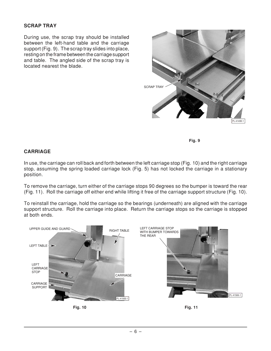
SCRAP TRAY
During use, the scrap tray should be installed between the
SCRAP TRAY ![]()
Fig. 9
CARRIAGE
In use, the carriage can roll back and forth between the left carriage stop (Fig. 10) and the right carriage stop, assuming the spring loaded carriage lock (Fig. 5) has not locked the carriage in a stationary position.
To remove the carriage, turn either of the carriage stops 90 degrees so the bumper is toward the rear (Fig. 11). Roll the carriage off either end while lifting it free of the carriage support structure (Fig. 10).
To reinstall the carriage, hold the carriage so the bearings (underneath) are aligned with the carriage support structure. Roll the carriage into place. Return the carriage stops so the carriage is stopped at both ends.
UPPER GUIDE AND GUARD |
|
| LEFT CARRIAGE STOP | |
RIGHT TABLE | ||||
|
| WITH BUMPER TOWARDS | ||
|
|
| ||
|
|
|
THE REAR
LEFT TABLE ![]()
LEFT
CARRIAGE
STOP
CARRIAGE
CARRIAGE
SUPPORT
| |
Fig. 10 | Fig. 11 |
– 6 –