Visit our website at
www.HobartWelders.com
| 187 558M |
January 2001
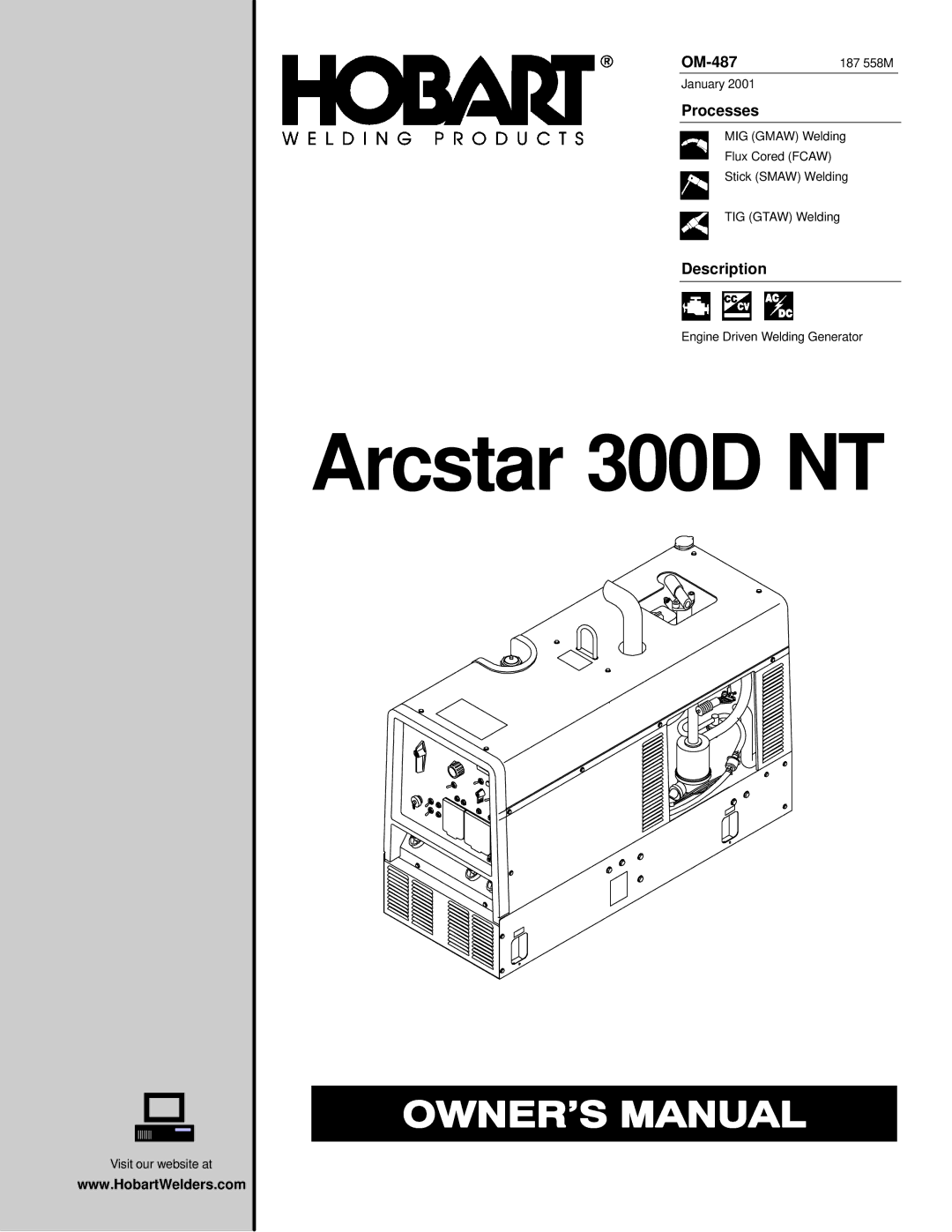
Processes
MIG (GMAW) Welding
Flux Cored (FCAW)
Stick (SMAW) Welding
TIG (GTAW) Welding
Description
Engine Driven Welding Generator
Visit our website at
www.HobartWelders.com
| 187 558M |
January 2001
MIG (GMAW) Welding
Flux Cored (FCAW)
Stick (SMAW) Welding
TIG (GTAW) Welding
Engine Driven Welding Generator