Manuals
/
Hobart Welding Products
/
Power Tools
/
Welding System
Hobart Welding Products
OM-487
manual
201
Models:
OM-487
1
41
60
60
Download
60 pages
28.64 Kb
38
39
40
41
42
43
44
45
Troubleshooting
Specifications
Install
Parts list
Electrical Diagram
Symbol Usage
Connecting The Battery
Dimension
Maintenance
Main Assembly
Page 41
Image 41
201 926
OM-487
Page 37
Page 40
Page 42
Page 41
Image 41
Page 40
Page 42
Contents
Description
OM-487
Processes
From Hobart to You
Table of Contents
Page
Arc Welding Hazards
Symbol Usage
Electric Shock can kill
ARC Rays can burn eyes and skin
Engine Hazards
Moving Parts can cause injury
Battery Explosion can Blind
Engine Exhaust Gases can kill
Engine Heat can cause fire
EMF Information
Principal Safety Standards
Radiation can cause interference
ARC Welding can cause interference
Consignes DE SÉ Curité Lire Avant Utilisation
Signification des symboles
UN Choc É Lectrique peut tuer
LES Fumé ES ET LES GAZ peuvent ê tre dangereux
DES Particules Volantes peuvent blesser les yeux
LE Soudage peut provoquer un in- cendie ou une explosion
DES PIÈ CES Chaudes peuvent provoquer des brû lures graves
LE Bruit peut affecter l’ouïe
’EXPLOSION DE LA Batterie peut
DES Organes Mobiles peuvent provoquer des blessures
LA Chaleur DU Moteur peut pro- voquer un incendie
LA Chute DE L’APPAREIL peut blesser
Information sur les champs é lectromagné tiques
Principales normes de sé curité
LE Soudage À L’ARC risque de provoquer des interfé rences
Consignes relatives aux stimulateurs cardiaques
Symbol Definitions
Specifications
Weld, Power, And Engine Specifications
Definitions
Fuel Consumption
Dimensions, Weights, And Operating Angles
Dimensions
Exceeding duty cycle can damage unit and void warranty
Auxiliary Power Curve
Duty Cycle
100% Duty Cycle at 290 Amperes DC
CC/DC Mode
CC/AC Mode
CV/DC Mode
Volt-Ampere Curves
Installing Welding Generator
Installation
Installing Exhaust Pipe
Do not lift unit from end Airflow Clearance
Engine Prestart Checks
13 mm Full Diesel Coolant Recovery Tank
Fuel Do not use gasoline. Gasoline will damage engine
Oil
Connecting To Weld Output Terminals
Connecting The Battery
Adding Coolant To Radiator
Connect negative
Remote 14 Receptacle Information
Selecting Weld Cable Sizes
Stop engine
Adjusting MIG Weld Puddle Consistency
To wet out weld puddle
To stiffen weld puddle
Place switch in Run position to operate most Gmaw equipment
Do not switch under load
Operating Welding Generator
Front Panel Controls
1nected to the remote 14 recep- tacle is running
Remote Amperage/Voltage Control
Auxiliary power decreases as weld current increases
Auxiliary Power Receptacles And Circuit Breakers
Open, contact Factory Authorized Service Agent
Operating Auxiliary Equipment
Australian Receptacle Option
Optional Auxiliary Power Receptacles
Gfci Receptacle Option
Receptacle
Wiring Optional 240 Volt Plug
Maintenance Label
Maintenance and Troubleshooting
20 h
Routine Maintenance
50 h
75 h
400 h
200 h
500 h
800 h
Servicing Air Cleaner
Stop engine and let cool
Servicing Engine Cooling System
Servicing Optional Spark Arrestor
Fuel Lines Replace fuel lines if cracked or worn
Servicing Engine Fuel And Lubrication Systems
Adjusting Fuel Solenoid Position
Adjusting Engine Speed
Stop screw is factory-set and should not be adjusted
Checking Fuel Solenoid
Checking Throttle Solenoid
Adjusting Throttle Solenoid
Check for non-binding
Solenoid in relaxed
Adjusting Weld/Power Speed
Making Engine Speed Adjustments
Adjusting Idle Speed
Overload Protection
Troubleshooting
Welding
Trouble Remedy
Check and clean air cleaner as necessary see Section
Low weld output Check control settings
Check engine speed, and adjust if necessary see Section
See engine manual
Engine
Auxiliary Power
Trouble Remedy
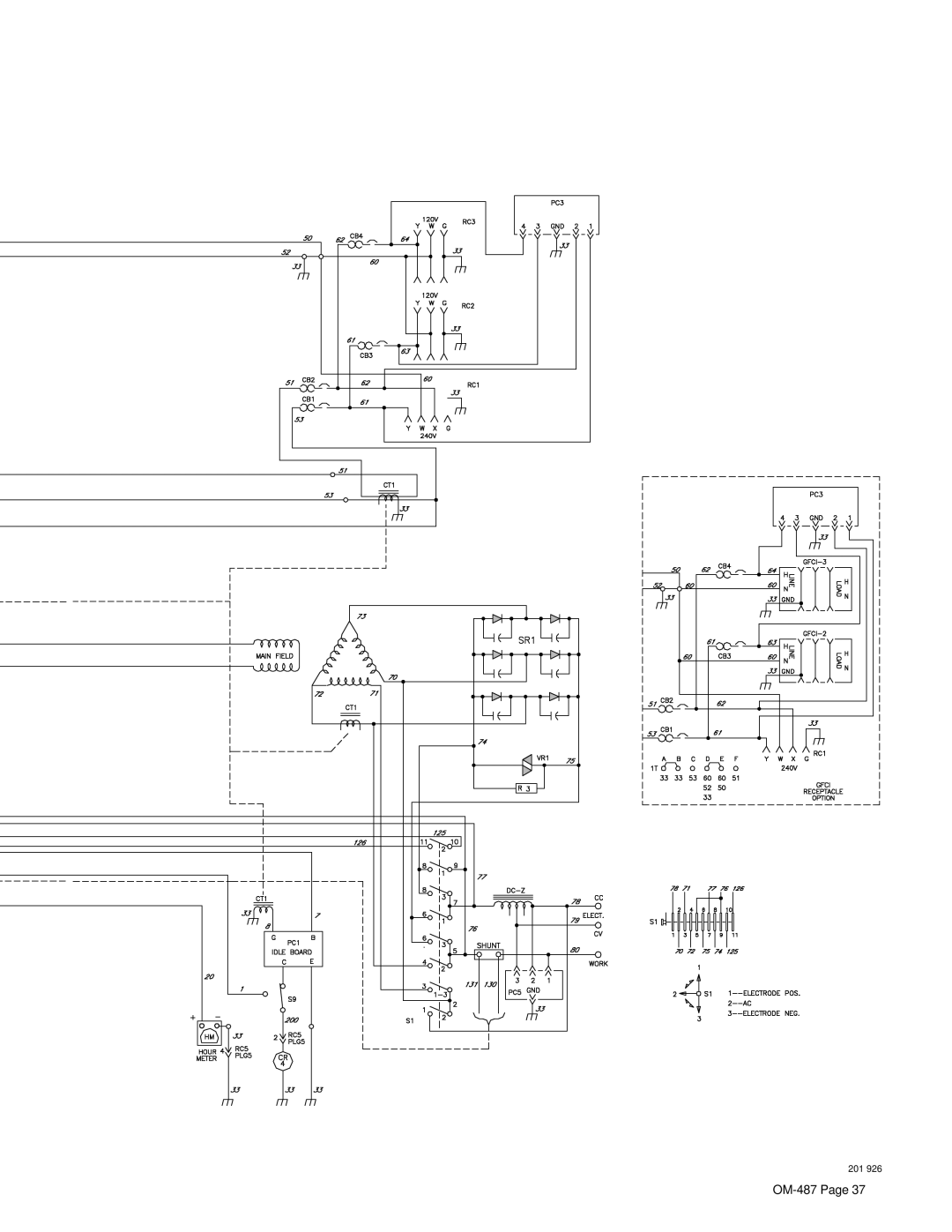
Circuit Diagram For Welding Generator
Electrical Diagram
201
Wetstacking
RUN-IN Procedure
Load Bank
Run-In Procedure Using Load Bank
Do not touch hot exhaust
Run-In Procedure Using Resistance Grid
Bank/grid
From flammables
Has this symbol
Auxiliary Power Guidelines
Selecting Equipment
Grounding Generator To Truck Or Trailer Frame
How Much Power Does Equipment Require?
Grounding When Supplying Building Systems
Earth ground if supplying
Use ground device as stated in electrical codes
Approximate Power Requirements For Farm/Home Equipment
Approximate Power Requirements For Industrial Motors
Industrial Motors Rating Starting Watts Running Watts
Farm/Home Equipment Rating Starting Watts Running Watts
Contractor Rating Starting Watts Running Watts
Approximate Power Requirements For Contractor Equipment
How Much Power Can Generator Supply?
Power Required To Start Motor
Single-Phase Induction Motor Starting Requirements
KVA/HP x HP x
Typical Connections To Supply Standby Power
Current Load Watts Amperes
Selecting Extension Cord Use Shortest Cord Possible
80- -2
Parts List
56- -3
Main Assembly
Dia Part Description
124
Hardware is common Not available unless listed
Panel, Front w/Components
Panel, Front w/Components -1 Item
Generator -1 Item
Support
Service
Call
Contact your Distributor for
Hobart Welding Products
Top
Page
Image
Contents