|
|
|
|
|
|
|
|
|
|
|
|
|
|
|
|
|
|
|
| H |
|
|
|
|
|
|
|
|
|
|
|
|
|
|
|
|
|
|
|
|
|
| A |
|
|
|
|
|
|
|
|
|
|
|
|
|
|
|
|
|
| |
|
|
|
|
|
|
|
|
|
|
|
|
|
|
|
|
|
|
|
| |
|
|
| B |
|
|
|
|
|
|
|
|
|
|
|
|
|
|
|
| |
|
|
|
|
|
|
|
| E |
|
|
|
|
|
|
|
|
| |||
|
|
|
|
|
| D |
|
|
|
|
|
|
|
|
| |||||
|
|
|
| C |
|
|
|
|
|
|
|
|
|
| ||||||
|
|
|
|
|
|
|
|
|
|
|
| J |
|
| ||||||
|
|
|
|
|
|
|
|
|
| F |
| G |
|
|
| |||||
|
|
|
|
|
|
|
|
|
|
|
|
|
| |||||||
|
|
|
|
|
|
|
|
|
|
|
|
|
|
| ||||||
|
|
|
|
|
|
|
|
|
|
| ||||||||||
FIGURE 1 |
|
|
|
| ||||||||||||||||
|
|
|
|
|
|
|
| |||||||||||||
|
|
|
|
|
|
|
|
|
|
|
|
| ||||||||
|
|
|
|
|
|
|
|
|
|
|
|
| ||||||||
|
|
|
|
|
|
|
|
|
|
|
|
|
|
|
|
|
| |||
| A. Logo Plate |
|
| J. | Remote Control |
|
|
|
| |||||||||||
| B. Front Grill |
|
|
|
| Housing |
|
|
|
|
|
| ||||||||
| C. Grill Caps |
|
| K. Remote Control |
|
|
|
| ||||||||||||
| D. Fan Blade Cap |
| L. Thumb Screw |
|
|
|
| |||||||||||||
| E. Fan Blade |
|
| M. Upper Pole |
|
|
|
| ||||||||||||
| F. | Rear Grill |
|
| N. Lower Pole |
|
|
|
| |||||||||||
|
|
|
| O. Base |
|
|
|
|
|
| ||||||||||
| G. Rear Grill |
|
| P. | Weight |
|
|
|
|
|
| |||||||||
| H. Motor Shaft |
|
| Q. Weight Nut |
|
|
|
| ||||||||||||
| I. | Motor Housing |
|
|
|
|
|
|
|
|
|
|
|
| ||||||
|
|
|
|
|
|
|
|
|
|
|
|
|
|
|
|
|
|
|
|
|
I
K
![]()
![]() L M
L M
N
O
![]() P
P
![]() Q
Q
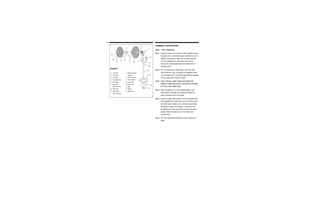
ASSEMBLY INSTRUCTIONS:
Base / Pole Assembly
Step 1: Insert the lower pole (longer of the 2 poles) through the base cover and twist the pole clockwise to lock in position. Be careful to align the
Step 2: Turn the base cover upside down (with the lower pole facing the floor) and place the weighted insert into the base cover. The pole threads will be exposed as they protrude through the insert.
NOTE: HOLD THE POLE, BASE COVER AND WEIGHTED INSERT IN ONE HAND WHILE TIGHTENING THE BASE NUT WITH THE OTHER HAND.
Step 3: Place the base nut on the threaded section and
Step 4: Insert the upper pole (shorter of the two poles) with the threaded joint (male end) into the hollow end of the lower pole (female end), until both poles meet. Be careful to align the cutaway / grooves on the threaded joint (male end) with the two protruding pieces inside the hollow end of the lower pole (female end).
Step 5: Turn the upper pole clockwise to lock it securely in place.
