4909 CPVC Conductivity Cell Insertion/Removal Assembly Operations Manual
Four Point Terminal Plate |
|
with | Five Point Terminal Board. |
| Each Terminal Will Accept |
| #16 Gage Max. Wire |
|
|
|
|
| 1000 ft. max. |
|
Temp. | RED | B |
|
| Note 3 |
|
|
| A | D | B |
| |
Comp. |
|
|
| |||
|
| D | Coax Cable Shield | |||
|
|
|
|
| ||
| GREEN | D | B | C |
| |
| A |
| ||||
|
| C |
|
|
| |
Cell | WHITE |
|
| C |
| |
BLACK |
|
|
|
|
| |
| A |
|
| Note 2 | W K SH G R | |
| Internal Cell Assembly |
|
| |||
|
|
|
|
| ||
| Configuration |
| View of Junction Box Head |
|
| |
|
|
| with Cap Removed |
| Note 1 | |
Cell Assembly Connections
I
4905 -
4973 I
4974 -
4908 I
4909 -
II | III |
|
| IV | V |
| VI | Conductivity/Resistivity |
| ||||||
|
|
| Analyzer | GND | |||||||||||
- |
| 333 | - |
| X1 |
|
|
|
|
|
| ||||
|
|
|
|
|
|
|
|
|
|
| |||||
| II | III |
|
| IV | V |
|
|
|
|
| Analyzer Input Connections |
|
| |
|
|
|
|
|
|
|
| ||||||||
333 | - X1 | - |
|
|
|
|
| VI VII |
|
|
| ||||
|
|
|
|
|
|
|
| ||||||||
|
|
|
|
|
|
|
| ||||||||
II | III |
| IV | V |
|
|
|
| |||||||
- |
| 333 | - |
| X1 |
|
|
|
|
|
|
|
|
| |
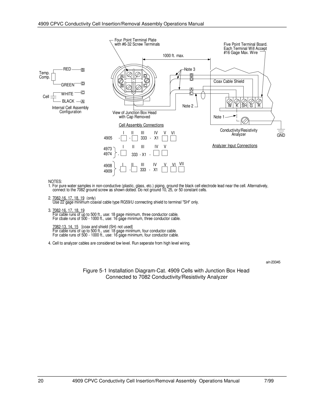
NOTES:
1.For pure water samples in
2.
Use 22 gage minimum coaxial cable type RG59/U connecting shield to terminal "SH" only.
3.
For cable runs of up to 500 ft., use: 18 gage minimum, three conductor cable.
For cbale runs of 500 - 1000 ft., use: 16 gage minimum, three conductor cable.
For cable runs of up to 500 ft., use: 18 gage minimum, four conductor cable.
For cable runs of 500 - 1000 ft., use: 16 gage minimum, four conductor cable.
4.Cell to analyzer cables are considered low level. Run seperate from high level wiring.
a/n 23345
Figure 5-1 Installation Diagram-Cat. 4909 Cells with Junction Box Head
Connected to 7082 Conductivity/Resistivity Analyzer
20 | 4909 CPVC Conductivity Cell Insertion/Removal Assembly– Operations Manual | 7/99 |