Platinization and Platinum Black
RED |
Temp. |
Comp. |
GREEN |
WHITE |
Cell |
BLACK |
Cell Assembly Connections |
Five Point Terminal Board.
Each Terminal Will Accept
#16 Gage Max. Wire
20 ft. max.
Red
Green
Black
White
Cell cable is approx. 0.250" (6.4mm) O.D. max. with 4 conductors of #18 AWG wire, 7 or 20 foot length.
SH
G
R
G
R
W
K
W
K
Note 1
#2 Temp(Note 5) Compensator
#1 Temp Compensator
Cell 2 (Note 5) Electrodes
Cell 1
Electrodes
4905 |
| I | II | III | IV | V | VI | ||||||
- |
| - |
| 333 | - X1 |
|
|
|
|
| |||
4973 |
| I | II | III |
| IV | V |
|
|
|
| ||
|
|
|
|
|
|
|
|
|
|
|
|
| |
4974 | - |
|
| 333 - X1 | - |
|
|
|
| VI VII | |||
|
|
|
|
| |||||||||
4908 |
| I | II | III |
| IV | V |
| |||||
4909 | - |
| - |
| 333 - | X1 |
|
|
|
|
| ||
|
|
|
|
|
|
|
|
|
|
|
|
| |
Cell Assembly Connections
I | II | III | IV | V VI |
Direct Cell to Analyzer Installation
20 ft. max. | 1000 ft. max. |
| Note 3 |
Red | R |
Green | G |
| |
Black | K |
White | W |
| Note 2 | |
Junction Box | ||
Coax Cable | ||
| ||
| Shield |
Conductivity/Resistivity
AnalyzerGND
Analyzer Input Connections
SH |
|
|
| |
G |
|
|
| #2 Temp (Note 5) |
|
|
| ||
R |
|
|
| Compensator |
|
|
|
| |
G |
|
|
| #1 Temp |
|
|
|
| |
R |
|
|
| Compensator |
|
|
| ||
W |
|
|
| Cell 2 (Note 5) |
|
|
| ||
K |
|
|
| Electrodes |
|
|
|
| |
W |
|
|
| Cell 1 |
|
| |||
|
|
| ||
|
|
|
| Electrodes |
4905 | - |
| - |
| 333 | - X1 |
|
|
|
| Cell to Analyzer Through Junction Box | |||
|
|
|
|
|
|
|
|
|
|
|
|
|
| Note 3 |
4973 |
| I | II | III |
| IV | V |
|
|
|
| |||
|
|
|
|
|
|
|
|
|
|
|
|
|
| |
4974 | - |
|
| 333 - X1 | - |
|
|
|
| VI VII | ||||
|
|
|
|
| ||||||||||
4908 |
| I | II | III |
| IV | V |
| ||||||
4909 | - |
| - |
| 333 - | X1 |
|
|
|
|
|
| ||
|
|
|
|
|
|
|
|
|
|
|
|
|
| |
K |
Note 1
Conductivity/Resistivity
AnalyzerGND
Analyzer Input Connections
NOTES:
1.For pure water samples in
2.
Use 22 gage minimum coaxial cable type RG59/U connecting shield to terminal "SH" only.
3.
For cable runs of up to 500 ft., use: 18 gage minimum, three conductor cable.
For cbale runs of 500 - 1000 ft., use: 16 gage minimum, three conductor cable.
For cable runs of up to 500 ft., use: 18 gage minimum, four conductor cable.
For cable runs of 500 - 1000 ft., use: 16 gage minimum, four conductor cable.
4.Cell to analyzer cables are considered low level. Run seperate from high level wiring.
5.If 2 Cells are to be applied, the same guidelines are applied to Cell 2 as wereused for Cell 1.
a/n 23346
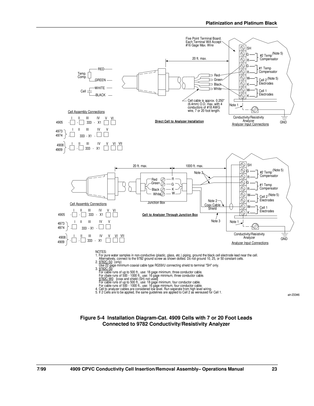
Figure 5-4 Installation Diagram-Cat. 4909 Cells with 7 or 20 Foot Leads
Connected to 9782 Conductivity/Resistivity Analyzer
7/99 | 4909 CPVC Conductivity Cell Insertion/Removal Assembly– Operations Manual | 23 |