General Information
Remove all packaging material.
Remove separate accessory box.
Remove the generator from carton.
Check all contents. If any parts are missing or damaged, locate an authorized dealer at
The generator requires some assembly prior to using it. If problems arise when assembling the generator, please call the Generator Helpline at
The wheels are designed to greatly improve the portability of the generator. You will need the following tools to properly install the accessory kit:
Ratchet and a 10mm socket
10mm box wrench
Refer to the instructions below and figures 1A, 1B, and 1C to install the handles, feet, and wheels. Note: the handle components are already
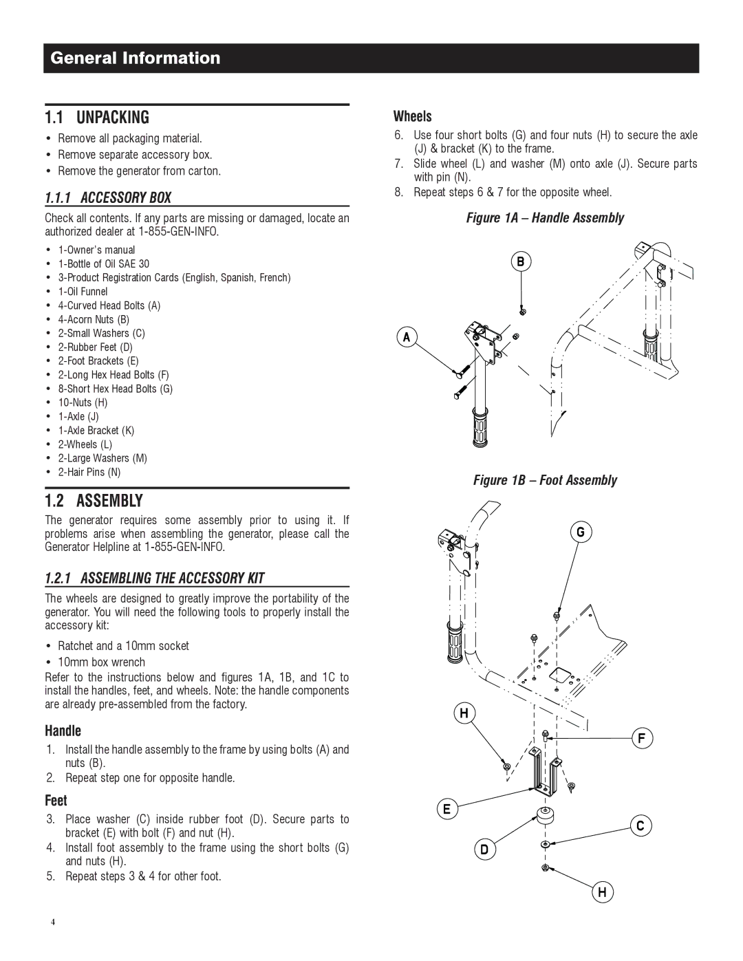
1.Install the handle assembly to the frame by using bolts (A) and nuts (B).
2.Repeat step one for opposite handle.
3.Place washer (C) inside rubber foot (D). Secure parts to bracket (E) with bolt (F) and nut (H).
4.Install foot assembly to the frame using the short bolts (G) and nuts (H).
5.Repeat steps 3 & 4 for other foot.
6.Use four short bolts (G) and four nuts (H) to secure the axle
(J) & bracket (K) to the frame.
7.Slide wheel (L) and washer (M) onto axle (J). Secure parts with pin (N).
8.Repeat steps 6 & 7 for the opposite wheel.
Figure 1A Handle Assembly
Figure 1B Foot Assembly
4