•Where the hob is not installed over a
Ventilation
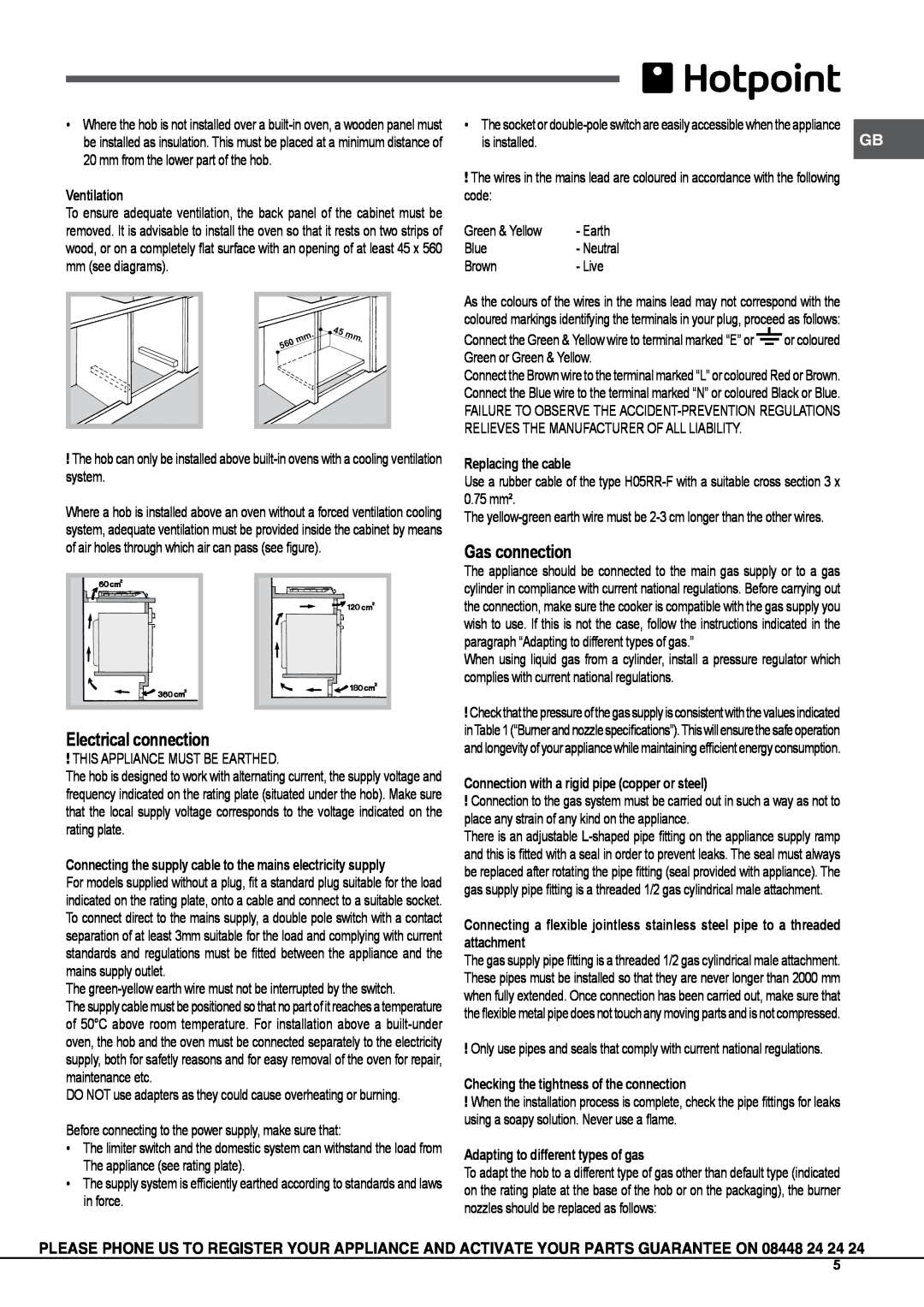
To ensure adequate ventilation, the back panel of the cabinet must be removed. It is advisable to install the oven so that it rests on two strips of wood, or on a completely flat surface with an opening of at least 45 x 560 mm (see diagrams).
. | 45 | mm. |
mm |
| |
560 |
|
|
!The hob can only be installed above
Where a hob is installed above an oven without a forced ventilation cooling system, adequate ventilation must be provided inside the cabinet by means of air holes through which air can pass (see figure).
Electrical connection
!THIS APPLIANCE MUST BE EARTHED.
The hob is designed to work with alternating current, the supply voltage and frequency indicated on the rating plate (situated under the hob). Make sure that the local supply voltage corresponds to the voltage indicated on the rating plate.
Connecting the supply cable to the mains electricity supply
For models supplied without a plug, fit a standard plug suitable for the load indicated on the rating plate, onto a cable and connect to a suitable socket. To connect direct to the mains supply, a double pole switch with a contact separation of at least 3mm suitable for the load and complying with current standards and regulations must be fitted between the appliance and the mains supply outlet.
The
The supply cable must be positioned so that no part of it reaches a temperature of 50°C above room temperature. For installation above a
DO NOT use adapters as they could cause overheating or burning.
Before connecting to the power supply, make sure that:
•The limiter switch and the domestic system can withstand the load from
The appliance (see rating plate).
•The supply system is efficiently earthed according to standards and laws in force.
• The socket or | GB |
is installed. |
!The wires in the mains lead are coloured in accordance with the following code:
Green & Yellow | - Earth |
Blue | - Neutral |
Brown | - Live |
As the colours of the wires in the mains lead may not correspond with the coloured markings identifying the terminals in your plug, proceed as follows:
Connect the Green & Yellow wire to terminal marked “E” or ![]() or coloured Green or Green & Yellow.
or coloured Green or Green & Yellow.
Connect the Brown wire to the terminal marked “L” or coloured Red or Brown. Connect the Blue wire to the terminal marked “N” or coloured Black or Blue.
FAILURE TO OBSERVE THE
Replacing the cable
Use a rubber cable of the type
The
Gas connection
The appliance should be connected to the main gas supply or to a gas cylinder in compliance with current national regulations. Before carrying out the connection, make sure the cooker is compatible with the gas supply you wish to use. If this is not the case, follow the instructions indicated in the paragraph “Adapting to different types of gas.”
When using liquid gas from a cylinder, install a pressure regulator which complies with current national regulations.
!Checkthat thepressure of thegas supply isconsistent withthevalues indicated inTable1(“Burnerandnozzlespecifications”).Thiswillensurethesafeoperation and longevity of your appliance while maintaining efficient energy consumption.
Connection with a rigid pipe (copper or steel)
!Connection to the gas system must be carried out in such a way as not to place any strain of any kind on the appliance.
There is an adjustable
Connecting a flexible jointless stainless steel pipe to a threaded attachment
The gas supply pipe fitting is a threaded 1/2 gas cylindrical male attachment. These pipes must be installed so that they are never longer than 2000 mm when fully extended. Once connection has been carried out, make sure that the flexible metal pipe does not touch any moving parts and is not compressed.
!Only use pipes and seals that comply with current national regulations.
Checking the tightness of the connection
!When the installation process is complete, check the pipe fittings for leaks using a soapy solution. Never use a flame.
Adapting to different types of gas
To adapt the hob to a different type of gas other than default type (indicated on the rating plate at the base of the hob or on the packaging), the burner nozzles should be replaced as follows:
PLEASE PHONE US TO REGISTER YOUR APPLIANCE AND ACTIVATE YOUR PARTS GUARANTEE ON 08448 24 24 24
5