1 | 1 | 2 | 3 |
4
2
3
5 | 6 |
|
|
|
|
|
|
|
|
|
|
| |
|
|
|
|
|
| |
|
|
|
|
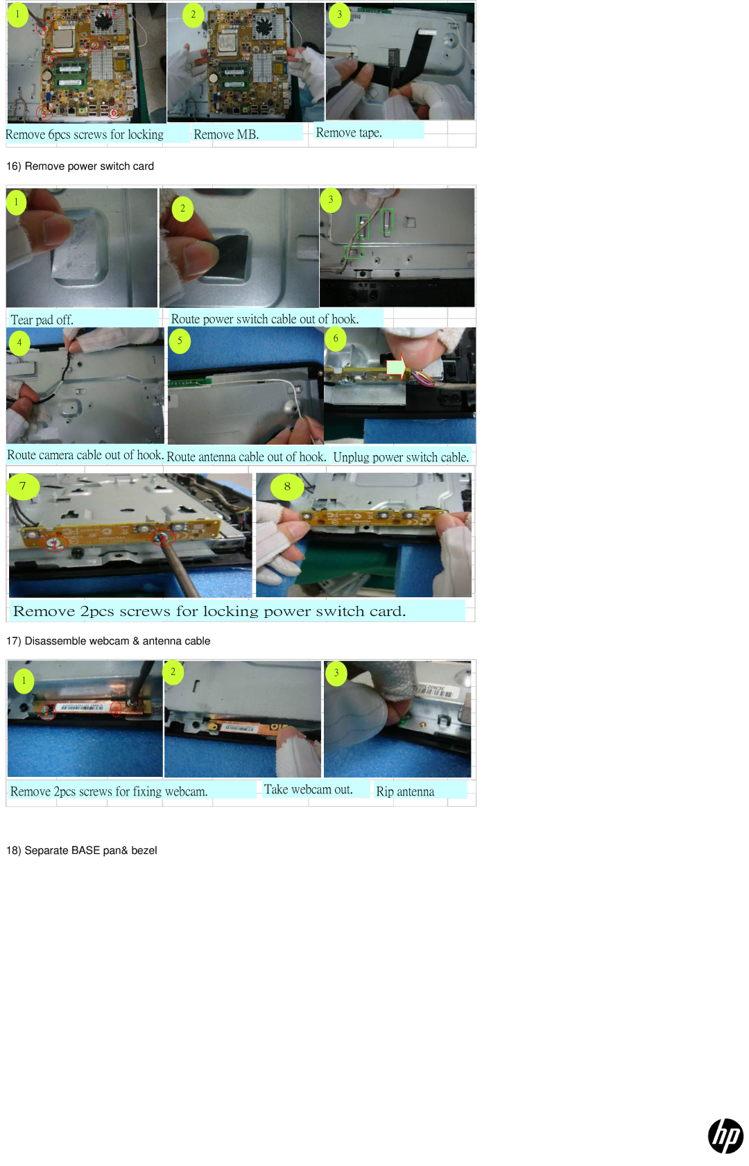
| Remove tape. |
|
Remove 6pcs screws for locking |
| Remove MB. |
|
| ||
| ||||||
|
|
|
|
|
|
|
16) Remove power switch card
1
2
3
| Tear pad off. |
|
| Route power switch cable out of hook. |
| |||
|
| |||||||
|
|
|
|
|
|
|
|
|
4 |
| 5 |
| 6 |
| |||
|
|
|
| |||||
|
|
|
|
|
|
|
|
|
|
|
|
|
|
|
|
|
|
|
|
|
|
|
|
|
|
|
|
|
|
|
|
|
|
|
|
|
|
|
|
|
|
|
|
|
|
|
|
|
|
|
|
|
|
|
|
|
|
|
|
|
|
|
|
|
|
|
|
|
|
|
|
|
|
|
|
|
|
|
|
|
Route camera cable out of hook. Route antenna cable out of hook. Unplug power switch cable.
7
8
1
2
Remove 2pcs screws for locking power switch card.
17) Disassemble webcam & antenna cable
1
2
3
1
2
|
| Take webcam out. |
|
|
Remove 2pcs screws for fixing webcam. |
|
| Rip antenna | |
|
|
18) Separate BASE pan& bezel
