Chart Environmental Chambers | System Installation |
suction into the blower in the back wall of the chamber and discharge from the top of the chamber.
❏Liquid Nitrogen Plumbing
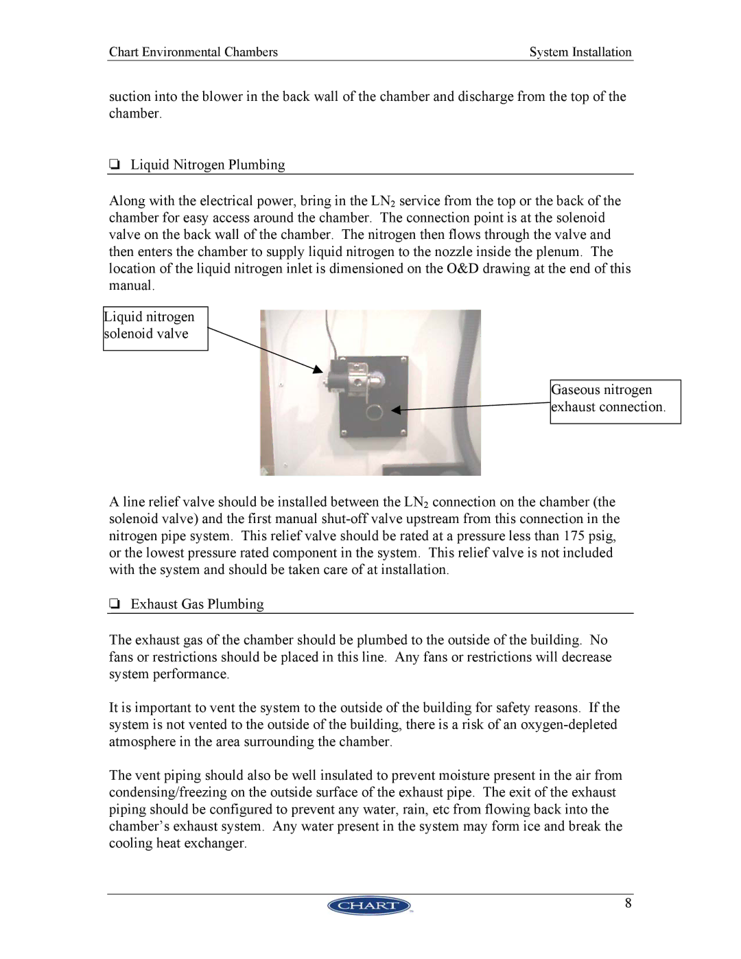
Along with the electrical power, bring in the LN2 service from the top or the back of the chamber for easy access around the chamber. The connection point is at the solenoid valve on the back wall of the chamber. The nitrogen then flows through the valve and then enters the chamber to supply liquid nitrogen to the nozzle inside the plenum. The location of the liquid nitrogen inlet is dimensioned on the O&D drawing at the end of this manual.
Liquid nitrogen solenoid valve
Gaseous nitrogen ![]() exhaust connection.
exhaust connection.
A line relief valve should be installed between the LN2 connection on the chamber (the solenoid valve) and the first manual
❏Exhaust Gas Plumbing
The exhaust gas of the chamber should be plumbed to the outside of the building. No fans or restrictions should be placed in this line. Any fans or restrictions will decrease system performance.
It is important to vent the system to the outside of the building for safety reasons. If the system is not vented to the outside of the building, there is a risk of an
The vent piping should also be well insulated to prevent moisture present in the air from condensing/freezing on the outside surface of the exhaust pipe. The exit of the exhaust piping should be configured to prevent any water, rain, etc from flowing back into the chamber’s exhaust system. Any water present in the system may form ice and break the cooling heat exchanger.
8