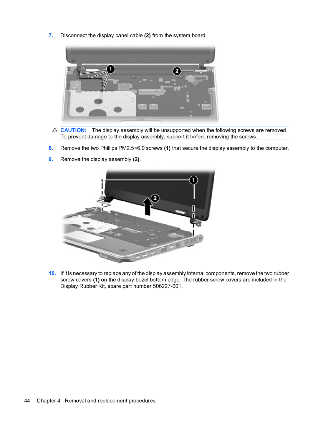
7.Disconnect the display panel cable (2) from the system board.
CAUTION: The display assembly will be unsupported when the following screws are removed. To prevent damage to the display assembly, support it before removing the screws.
8.Remove the two Phillips PM2.5×6.0 screws (1) that secure the display assembly to the computer.
9.Remove the display assembly (2).
10.If it is necessary to replace any of the display assembly internal components, remove the two rubber screw covers (1) on the display bezel bottom edge. The rubber screw covers are included in the Display Rubber Kit, spare part number
44 Chapter 4 Removal and replacement procedures