7.Keyboard (see Keyboard on page 47)
8.Top cover (see Top cover on page 49)
9.USB board (see USB board on page 56)
10.Display assembly (see Display assembly on page 59)
11.Power connector (see Power connector on page 58)
12.System board (see System board on page 66)
13.Fan/heat sink assembly (see Fan/heat sink assembly on page 70) Remove the processor:
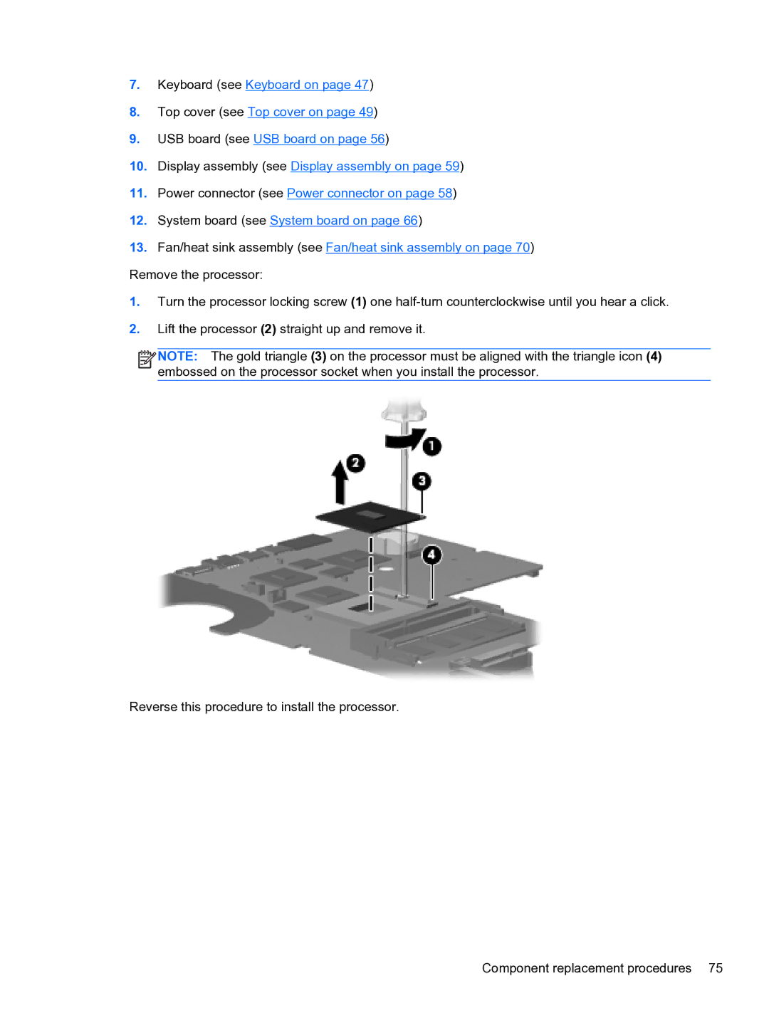
1.Turn the processor locking screw (1) one
2.Lift the processor (2) straight up and remove it.
![]()
![]()
![]()
![]() NOTE: The gold triangle (3) on the processor must be aligned with the triangle icon (4) embossed on the processor socket when you install the processor.
NOTE: The gold triangle (3) on the processor must be aligned with the triangle icon (4) embossed on the processor socket when you install the processor.
Reverse this procedure to install the processor.
Component replacement procedures 75